Motor-driven quick bench clamp

A fast, vise technology, applied in vices, manufacturing tools, etc., can solve problems such as troublesome operation and complex structure, and achieve the effects of convenient operation, reduced labor intensity, and fast moving speed.

Active Publication Date: 2012-07-11
NANTONG ZHONGYI BOILER EQUIP
View PDF8 Cites 9 Cited by
  • Summary
  • Abstract
  • Description
  • Claims
  • Application Information

AI Technical Summary

Problems solved by technology

[0007] In order to solve the problems of complex structure and cumbersome operation in the prior art, the present invention provides an electric fast vise, which can effectively reduce labor intensity, improve work efficiency, and quickly clamp the workpiece without manually driving the vise.

Method used


Image

  • Motor-driven quick bench clamp
  • Motor-driven quick bench clamp
  • Motor-driven quick bench clamp

Examples


Embodiment Construction

[0016] In order to make the technical means, creative features, goals and effects achieved by the present invention easy to understand, the present invention will be further elaborated below in conjunction with specific embodiments and illustrations.

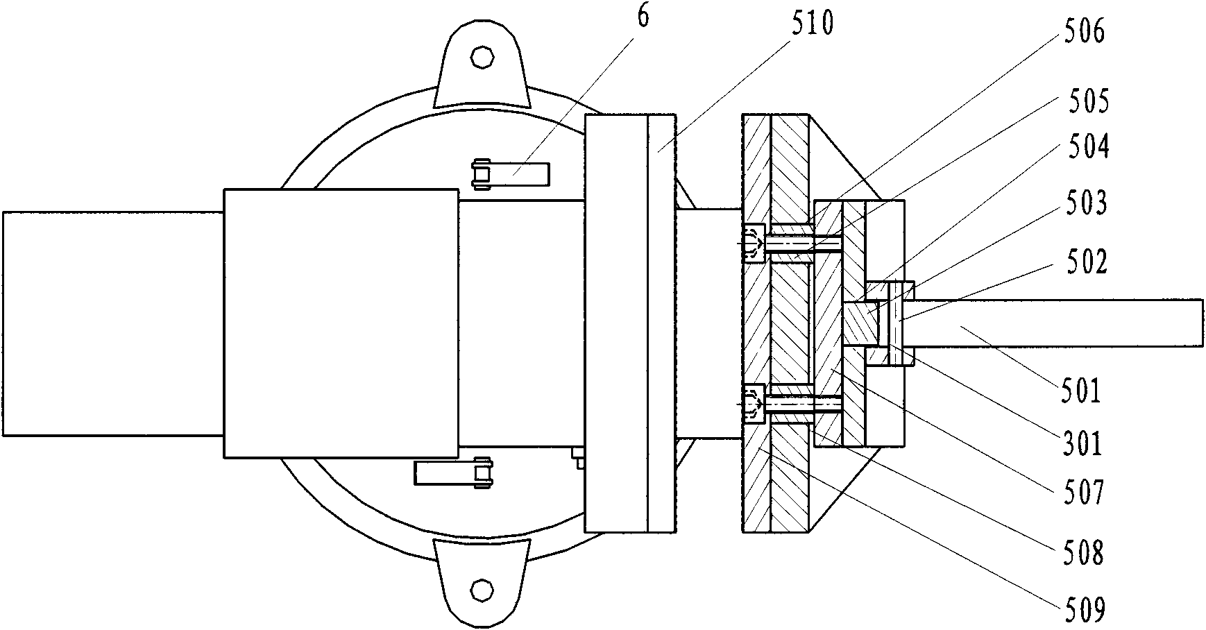
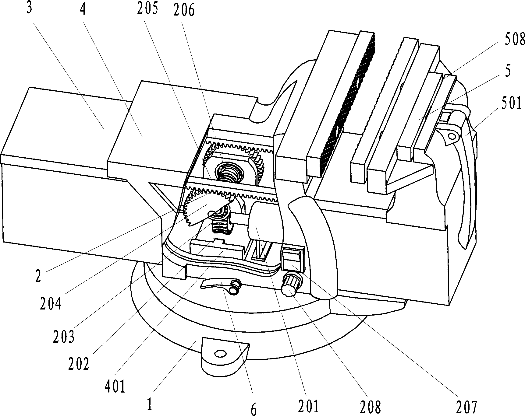
[0017] Such as figure 1 As shown, an electric fast vise is composed of a base 1 , a fixed vise body 4 , a locking handle 6 , a movable vise body 3 , a transmission system 2 and a clamping device 5 . Wherein, the base 1 is connected with the fixed pliers 4 through the locking handle 6; the fixed pliers 4 is provided with a bearing seat 401, and the bearing seat 401 is fixedly connected with the fixed pliers 4 by welding; the movable pliers 3 is connected with the fixed pliers body 4 through the transmission system 2. The upper end of the movable pliers body 3 is provided with two clamping handle connection holes 301 and a U-shaped groove 508, and the U-shaped groove 508 is close to the clamping handle connection hole 301. A push...


PUM


Abstract

The invention relates to a motor-driven quick bench clamp, which belongs to the field of fixtures. The motor-driven quick bench clamp is composed of a base, a fixed pliers body, a locking handle, a transmission system and a clamping device, wherein the base and the fixed pliers body are connected by the locking handle; a movable pliers body is connected with the fixed pliers body by the transmission system; the transmission system is meshed with gears and racks by a worm-and-gear transmission mechanism to move to drive the movable pliers body to move; the clamping device is installed on the upper end of the movable pliers body; the transmission system is used for regulating distance between a first locating block and a second locating block to quickly move the movable pliers body; the worm-and-gear transmission mechanism is used for realizing the self-locking function of a workpiece after the workpiece is quickly and tightly clamped between the first locating block and the second locating block; and the clamping device is used for further quickly clamping the workpiece. The motor-driven quick bench clamp has the advantages that the structure is compact, the design is smart, the movable pliers body can be moved quickly, the operation is convenient and the like, time and effort are saved, the labor intensity can be effectively lowered, and the working efficiency is improved.

Description

technical field [0001] The invention belongs to the field of clamps, in particular to an electric fast vise. Background technique [0002] The common vise currently used all drives the movable vise body by rotating the screw rod to adjust the distance between the two jaws of the vise, so as to realize the advancement and retreat of the vise and the clamping of the workpiece. The main disadvantage of this type of vise is that it is difficult to quickly adjust the distance between the two jaws of the vise according to the size of the workpiece. Rod, labor intensity is big, jaw moving speed is slow, and work efficiency is low. [0003] Patent No. 92241164.6 discloses a push-pull fast clamping bench vise, which is fixed by making a ratchet bar on the upper end of the sliding pliers body, installing a ratchet wheel on the fixed pliers body, and rotating the ratchet by twisting. Sliding pliers, the upper end of the sliding pliers is equipped with a micro-motion pliers, and the m...

Claims


Application Information

Patent Timeline
Patent Type & Authority Applications(China)
IPC IPC(8): B25B1/02B25B1/18
Inventor 王成军沈豫浙汪兵
Owner NANTONG ZHONGYI BOILER EQUIP
Why Eureka
Try Eureka