Horizontal type bending machine used for forming annular piece

A technology of bending machine and ring parts, applied in the field of equipment for forming large metal ring parts, can solve the problems of blank feeding, inability to form large ring parts, difficult forming operations, etc. Even wear effect

Inactive Publication Date: 2014-05-07
HARBIN INST OF TECH
View PDF7 Cites 0 Cited by
  • Summary
  • Abstract
  • Description
  • Claims
  • Application Information

AI Technical Summary

Problems solved by technology

[0006] The purpose of the present invention is to solve the problem that the prior art cannot form large-scale ring parts and the problems of blank feeding and forming operation are difficult when using the existing vertical hydraulic press to form large-scale ring parts, and then provide a horizontal machine for ring-shaped part forming. bending machine

Method used


Image

  • Horizontal type bending machine used for forming annular piece
  • Horizontal type bending machine used for forming annular piece
  • Horizontal type bending machine used for forming annular piece

Examples


specific Embodiment approach 1

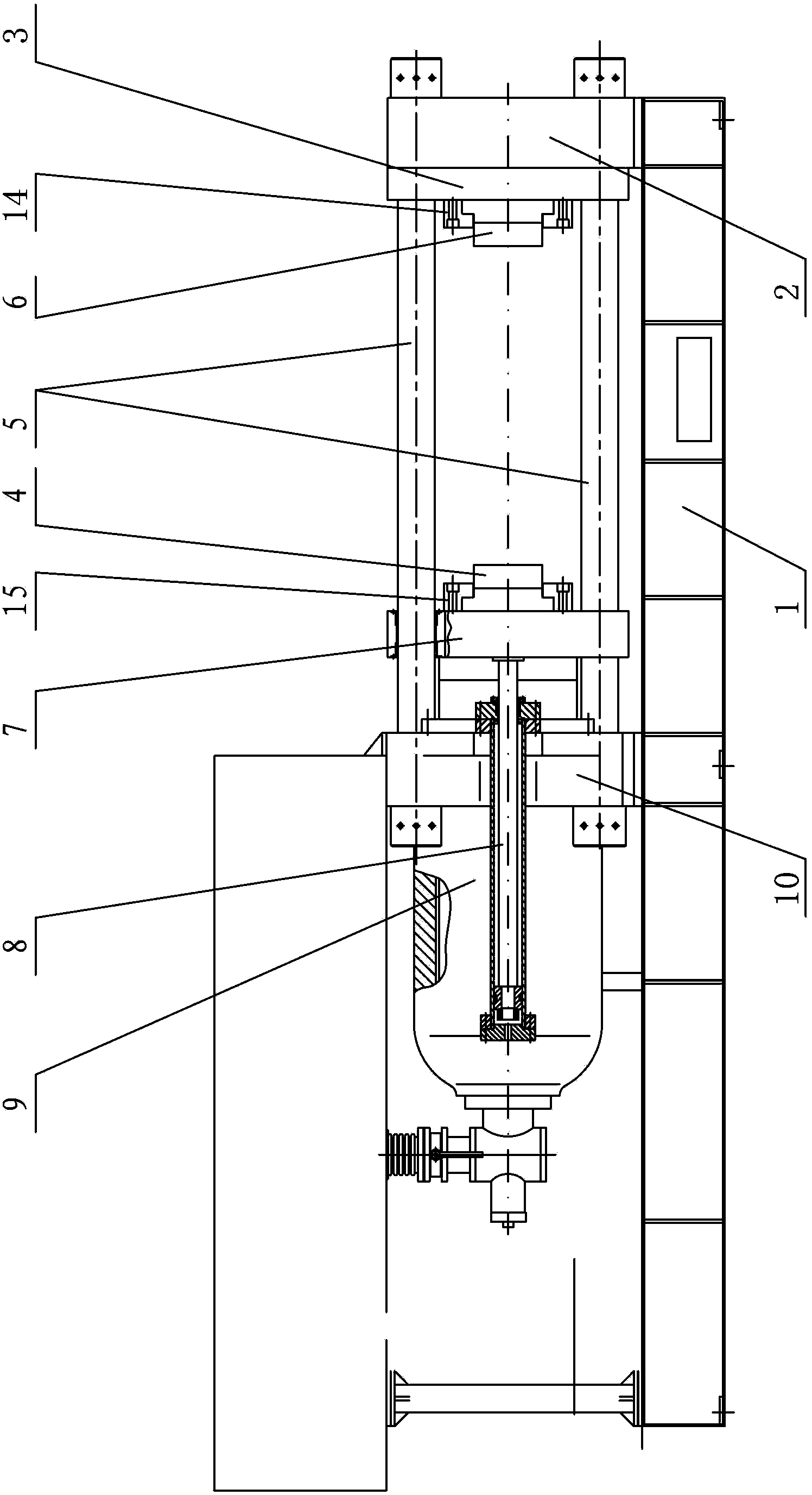
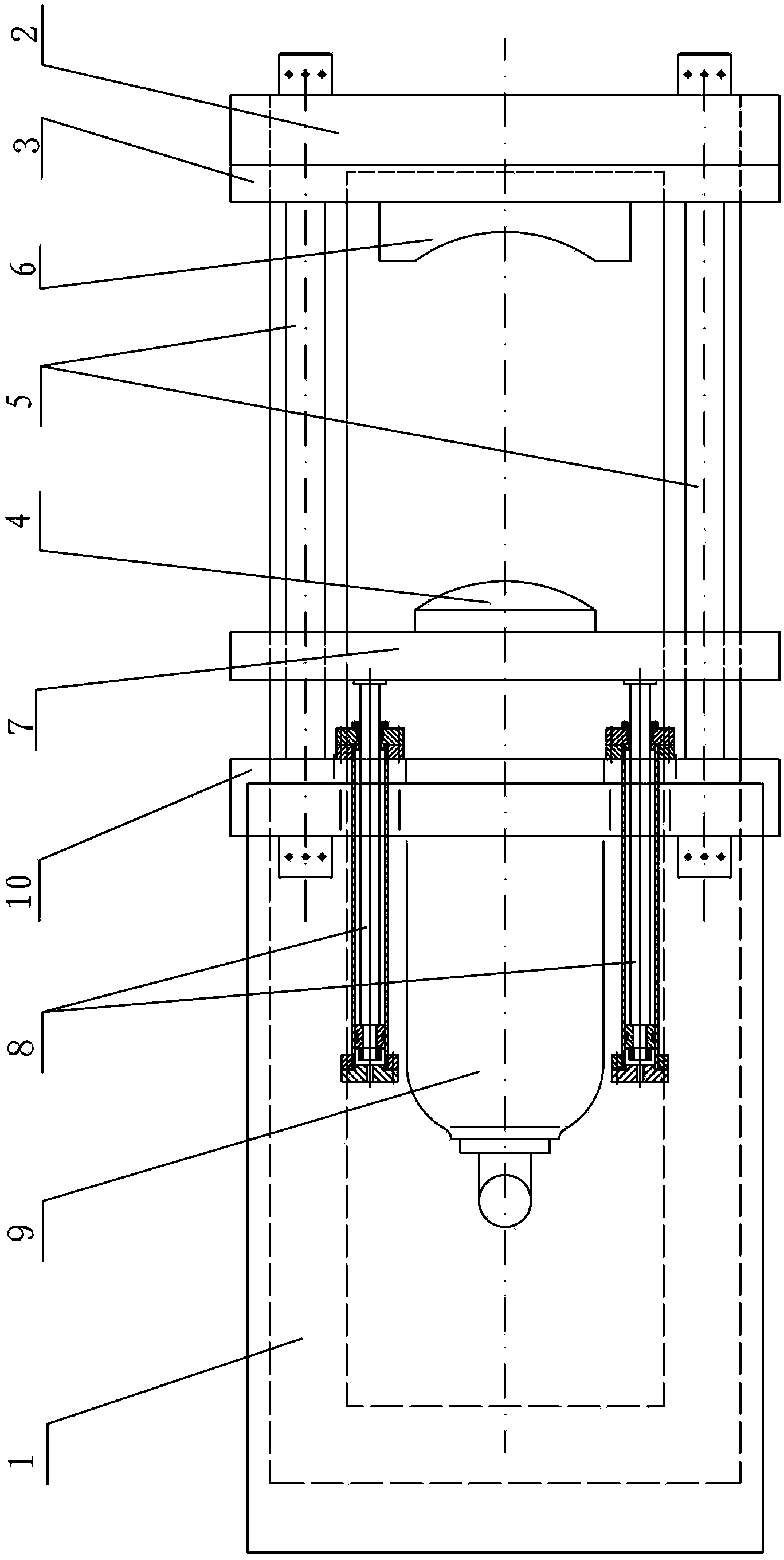
[0010] Specific implementation mode one: combine figure 1 and figure 2 Describe this embodiment, a horizontal bending machine for ring forming in this embodiment includes a frame 1, a first beam 2, a second beam 10, a working platform 3, a die 6, a punch 4, and a movable platform 7. The main hydraulic driving device 9, two side hydraulic driving devices 8 and four horizontal columns 5, the working platform 3, the first beam 2, the second beam 10 and the main hydraulic driving device 9 are horizontally installed on the upper surface of the frame 1 Above, the first crossbeam 2 and the second crossbeam 10 are arranged side by side along the length direction of the frame 1, the first crossbeam 2 and the second crossbeam 10 are provided with four horizontal columns 5 along the length direction of the frame 1, and the movable platform 7 The working platform 3 is located between the first beam 2 and the second beam 10, four horizontal columns 5 are pierced with a movable platform 7...

specific Embodiment approach 2

[0012] Specific implementation mode two: combination figure 1 To illustrate this embodiment, the bending machine described in this embodiment further includes a first press plate 15 , and the punch 4 is connected to the movable platform 7 through the first press plate 15 provided on the punch 4 . With such arrangement, the connection is firm and stable, which is convenient for fixing the punch. Meet the design requirements and actual needs. Others are the same as in the first embodiment.

specific Embodiment approach 3

[0013] Specific implementation mode three: combination figure 1 To illustrate this embodiment, the bending machine described in this embodiment further includes a second press plate 14 , and the die 6 is connected to the working platform 3 through the second press plate 14 provided on the die 6 . With such arrangement, the connection is firm and stable, which is convenient for fixing the die. Meet the design requirements and actual needs. Others are the same as in the first or second embodiment.

[0014] work process

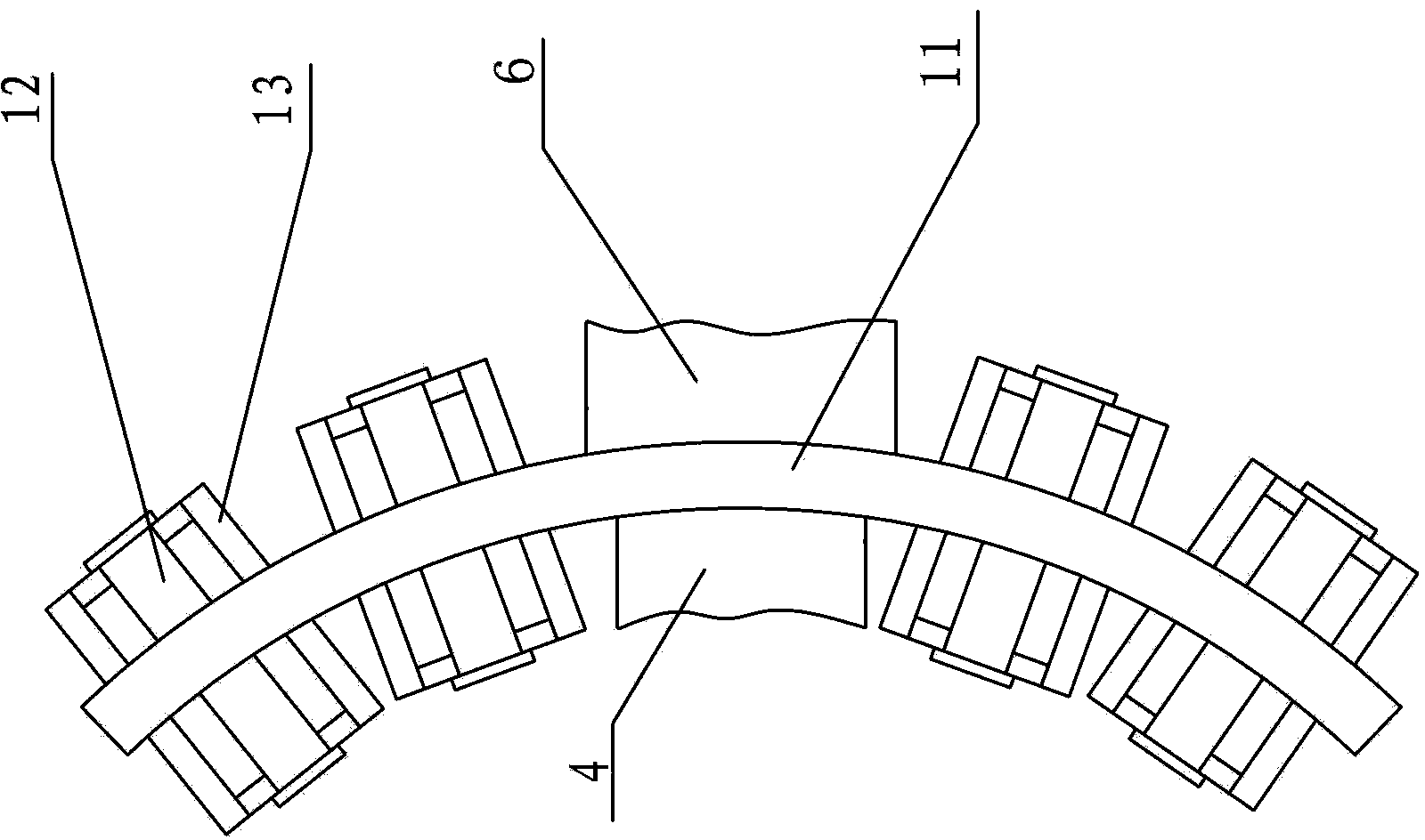
[0015] combine Figure 1-Figure 5 To illustrate the working process of the present invention, when the ring is pressed and formed, the blank 11 is horizontally placed between the punch 4 and the die 6, and the blank 11 is placed on the cylindrical rolling body 12 arranged on the bracket 13 of the movable support frame , the number and placement angle of the movable support frame can be adjusted and placed according to the size and bending radius of the bent ...


PUM


Abstract

The invention relates to a large metal piece forming device, and particularly relates to a horizontal type bending machine used for forming an annular piece. The horizontal type bending machine solves the problems in the prior art that no large annular pieces can be formed, and the blank feeding and forming operations are difficult when the existing vertical type hydropress is adopted to form large annular pieces. The horizontal type bending machine comprises a rack, a first beam, a second beam, a working platform, a concave die, a convex die, a movable platform, a main hydraulic driver, two side hydraulic drivers, and four horizontal columns, wherein the working platform, the first horizontal beam, the second horizontal beam and the main hydraulic driver are horizontally arranged on the upper surface of the rack, a connected movable platform is arranged between a main drive rod and the convex die of the main hydraulic driver, a working platform is arranged between the first beam and the concave die, and side drive rods of the two side hydraulic drivers are respectively connected with the movable platform. The horizontal type bending machine provided by the invention is used for forming annular pieces.

Description

technical field [0001] The invention relates to a large metal piece forming equipment, in particular to a large metal ring piece forming equipment. Background technique [0002] Ring parts are widely used in metallurgy, petrochemical, aerospace, aviation and other industries. The existing manufacturing technologies of ring parts mainly include horse frame reaming, rolling and rolling method and steel plate cutting method. [0003] Horse frame reaming is to put the blank on the mandrel, hammer the blank with the upper anvil on the press or forging hammer, and produce elongation along the circumferential direction, so that the wall thickness of the forging is thinned, and the inner and outer diameters are increased at the same time, so that To meet the required diameter and size requirements, and then complete the manufacture of the cross section of the ring by turning and other mechanical processing methods, the disadvantages are large diameter deviation, uneven wall thickne...

Claims


Application Information

Patent Timeline
Patent Type & Authority Patents(China)
IPC IPC(8): B21D3/00
Inventor 滕步刚苑世剑
Owner HARBIN INST OF TECH
Why Eureka
Try Eureka