Golf club head wear indicator
A golf club head and club face technology, applied to golf balls, golf clubs, rackets, etc., can solve the problems of loss of rigidity, energy dissipation, etc.
Inactive Publication Date: 2012-08-22
NIKE INTERNATIONAL LTD
9 Cites 0 Cited by
AI-Extracted Technical Summary
Problems solved by technology
In addition, the hosel can lose some of its rigidity, which leads to ...
Abstract
A golf club with a golf club head having a wear indicator is provided. The wear indicator may be located on the club head face, the hosel, the sole portion or the rear portion of the club head body. Also, multiple wear indicators may be provided on separate portions of the club head. Inserts may be used to provide a wear indicating portion. A coating may be provided to serve as a wear indicator.
Application Domain
Golf clubsRacket sports
Technology Topic
EngineeringGolf club +2
Image
Examples
- Experimental program(1)
Example Embodiment
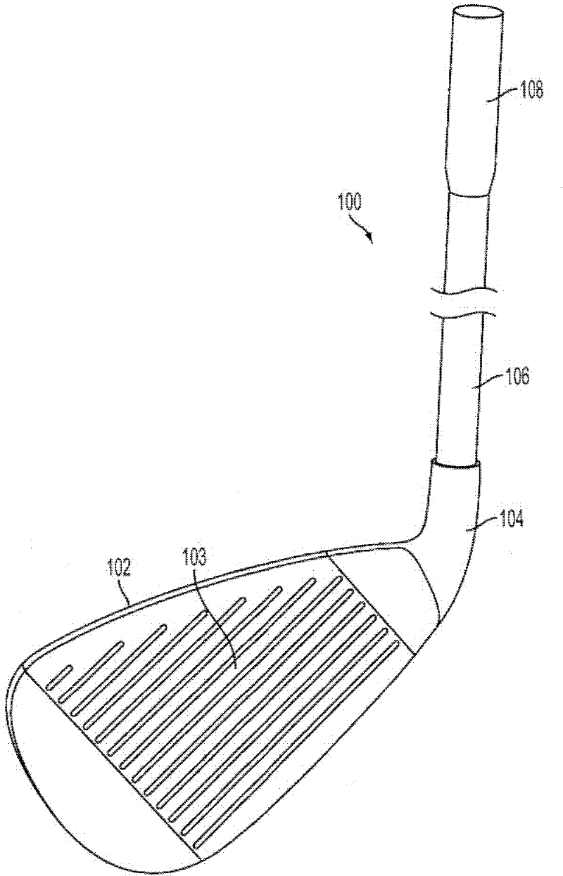
[0018] In the following description of various exemplary structures in accordance with the present invention, reference is made to the accompanying drawings, which form a part hereof, and in which various exemplary items, including one or more golf balls, are shown by way of example A shaft or golf club head structure. In addition, it is to be understood that other specific arrangements of parts and structures may be utilized, and structural as well as functional modifications may be made without departing from the scope of the present invention. Although the terms "top," "bottom," "front," "rear," "side, "back," etc. are used herein to describe various exemplary features and elements of the invention, the The terminology is for reasons of convenience only, and is exemplarily based on the exemplary orientation shown in the drawings or the orientation in common use. In addition, the term "plurality" as used herein designates any number greater than one, as desired But separate or combined, to infinity. Any part of this description should not be construed as requiring a three-dimensional orientation of a specific mechanism to fall within the scope of this disclosure. However, aspects of the present invention can be used for several golf clubs Any of these, including iron-type clubs, wood-type golf clubs, hybrid-type golf clubs, putter-type golf clubs, etc., and nothing in the specification or drawings should be construed as The invention is limited to the specific clubs described.
[0019] Generally, the present disclosure relates to golf striking devices, such as golf club heads and golf clubs, putter heads, putters, and the like. The golf ball striking device according to at least some examples of this invention may include a club head and a ball striking surface. Some of the more specific aspects relate to irons and iron club heads; iron-type hybrid clubs and club heads; wood-type golf clubs and club heads, including drivers, fairway woods, wood-type hybrid clubs, etc. ; putters and putter heads; etc.
[0020] According to various aspects of the present invention, the golf ball striking device may be formed from one or more of a variety of materials, such as metals (including metal alloys), ceramics, polymers, composites (including fiber-reinforced composites) and wood, and may be formed in one of a variety of configurations without departing from the scope of this disclosure. In one illustrated embodiment, some or all of the components of the head (including at least a portion of the face and the body of the head) are made of metal. It should be understood that the head may include components made from several different materials, including graphite, carbon-fiber composites, and other composite materials. Furthermore, the members can be formed by a variety of forming methods. For example, metal components (such as titanium, aluminum, titanium alloys, aluminum alloys, steel (including stainless steel), etc.) may be formed by forging, molding, casting, stamping, machining, and/or other known techniques. In another example, composite components such as carbon fiber-polymer composites may be fabricated by a variety of composite processing techniques, such as prepreg processing, powder-based techniques, mold infiltration, and/or other known known technology.
[0021] Examples of at least some ball striking devices relate to golf club head structures, including heads for iron-type golf clubs and wood-type clubs, including long iron-type clubs (eg, driving irons, zero irons to five irons, and mixed-type golf clubs), short iron types (such as six irons to pitching wedges, and sand wedges, lob wedges, relay wedges, and /or other wedges), and wood-type golf clubs such as driver and fairway woods, and putters. The device may comprise a one-piece construction or a multi-piece construction.
[0022] With reference to the drawings and the discussion below, example golf clubs and golf club heads in accordance with this invention are described. As mentioned above, the golf clubs and club head structures described herein are described as iron-type golf clubs. However, the present invention is not limited to the precise arrangements disclosed herein, but is generally applicable to golf clubs, including wood-type clubs, hybrid clubs, and the like.
[0023] Figure 1A and 1B An example of an iron-type golf club 100 and/or golf club head 102 is generally shown. The golf club head 102 in this example includes a body 101 , a face 103 and a hosel 104 . In addition to the golf club head 102 , the overall golf club structure 100 includes a shaft member 106 received in and/or inserted into and/or through the hosel region 104 , and a grip or handle attached to the shaft member 106 component 108 . The body 101 includes a sole portion 105 and a back surface 107 opposite the face 103 . In this example, body 101 includes face 103 . It will be appreciated that known golf club head midface panels are replaceable and coupled to the main portion of the body via adhesive, forging, and other known coupling methods. For immediate disclosure, the replaceable face plate can be considered part of the body. Alternatively, if desired, the outer hosel 104 may be absent, and the shaft member 106 may be inserted directly into and/or otherwise attached to the head member 102 (eg, by being disposed on top of the club head 102 body) openings in the interior, through an interior hosel member (eg, disposed within the interior cavity defined by the club head 102), etc.).
[0024] The shaft member 106 may be received, joined, and/or attached to the club head 102 in any suitable or desired manner, including conventional manners known and used in the art, without departing from this invention. As a more specific example, the shaft member 106 may be joined and/or diametrically joined to the club head structure 102 via the hosel member 104 and the club head 102, eg, via an adhesive, glue, welding, brazing, Mechanical connectors (such as threads, securing elements, etc., including selectively releasable mechanical connectors), etc.; receiving sleeves or elements through the shaft extending into the club head 102; and the like. The shaft member 106 may also be made of any suitable or desired material, including materials conventionally known and used in the art, such as graphite-based materials, composite or other non-metallic materials, steel materials (including stainless steel), aluminum materials, Other metal alloy materials, polymers, combinations of various materials, etc. Additionally, the grip or handle member 108 may be attached to the shaft member 106, engage with the golf club shaft 106, and/or extend from the golf club shaft 106 in any suitable or desired manner, including Conventional means are known in the art and used, eg, using adhesives or glues; via welding, soldering, adhesives, etc.; via mechanical connectors (eg, threads, fixing elements, etc.); and the like. As another example, if desired, the grip or handle member (108) may be integrally formed with the shaft member as a unitary, one-piece structure. Additionally, any desired grip or handle member material may be used without departing from this invention, including exemplarily rubber materials, leather materials, including cords or other fabric materials embedded therein of rubber or other materials, polymeric materials (synthetic or natural), cork materials, etc.
[0025] Figure 2AIron-type golf club head 102 is shown, including cavities 115a, 115b, and 115c, which are configured to receive inserts and form part of face 103, and cavity 115d, which is configured to The head 102 receives an insert therein and forms part of the hosel 104). Cavity 115a is provided in toe region 109 of club head face 103 . Cavities 115b are provided between adjacent grooves on the club head face 103 . In this example, three cavities 115b are provided between trenches 113a and 113b, and three additional cavities 115b are provided between trenches 113c and 113d. Also, the cavity 115c is provided in the heel region 111 of the club head face 103 . It will be appreciated that any number of cavities 115a, 115b, 115c and 115d may be provided, from one to multiple cavities. Also, one or more cavities may be positioned at any desired location on the club head face 103 and/or hosel 104 . For example, one cavity 115c may be provided in the hosel region and no other cavity is provided. Also, the cavity 115d may be provided in the hosel without other cavities on the hosel 104 or on the club head face 103, or with one or more other cavities.
[0026] Figure 2A Two exemplary inserts 112 are shown for insertion into respective cavities 115a. Other inserts (not shown) similar to insert 112 may be inserted into other cavities 115a, 115b, 115c, and 115 in club head 102, for example. It will be appreciated that the insert and cavity may have different shapes and sizes. The size of the cavity 115b disposed between adjacent formations may be limited by the space between the grooves and the need for structural compromises to avoid the effect of the grooves.
[0027] Insert 112 may be provided as a wear indicator to allow an individual, such as a golfer, to understand the degree of wear that has occurred on the club. For example, the insert 112 may indicate that the face has worn enough to affect club performance, or that the COR (Coefficient of Recovery) has decreased, ie, the energy transfer from the club head 102 to the ball has decreased to a point where it can affect the performance of the golf ball by the club. The degree of teleportation distance on head impact. The amount of stress and stress that a club head experiences through repeated impacts over long periods of time contributes to the degradation of club head performance. Here, the goal is to inform the golfer of the degree of deterioration through the wear indicator function.
[0028] image 3 An exemplary insert 112 is provided, which can be divided into two regions 122 , 124 . Regions 122, 124 each include a variable viscosity material that remains separated from each other in the absence of pressure. However, when the pressure acting on the regions of the insert 112 exceeds the threshold pressure, the materials in the respective regions 122, 124 mix together. A discussion of these materials and their uses is provided in US Patent No. 7,353,770. The two different regions may have distinct visual appearances that differ from each other so that when the materials are mixed together, the golfer can visually recognize the difference from the materials in the regions 122, 124 when they are not mixed. For example, the boundary 123 between the regions 122, 124 and the remainder of the club head 102 (ie, the toe portion 109, the heel portion 111, the hosel portion 104) blend together prior to repeated impact with the golf ball. Over time, due to repeated impacts with the face 103 of the club head 102, the regions 122, 124 mix or spread together, and the appearance of the insert 112 gradually changes to be integral with the face 103 and/or hosel 104 Contrast (eg, distinct color differences, differences in color saturation, shades, or patterns, etc.). By calibrating the degree of mixing between the two regions 122 , 124 , the degree of wear that the club has experienced can be reflected by the degree of contrast between the insert 112 and the rest of the golf club head 102 . One of ordinary skill in the art will understand that regions 122 and 124 may be made of a variety of known materials that tend to mix to a greater degree when under pressure or stress. In one aspect, the regions 122, 124 may be made of viscoplastic or non-Newtonian liquids. Viscoplastics behave like solids below a certain stress level, such as yield stress. Above this stress level, viscoplastics behave like viscous liquids. Regions 122 and 124 may be made of another non-Newtonian mechanical liquid, such as a pseudoplastic, which may also be referred to as a shear thinning liquid, which produces a reduced viscosity as the shear rate increases. The insert 112 will in most respects have a surface coating so that the non-Newtonian fluid is not directly exposed to the environment. The surface coating of the insert 112 on the face 103 is generally durable and able to withstand repeated impacts of the club head 103 and golf ball. In one example, the surface coating may be a transparent polyurethane coating similar to the material used in golf balls. The surface coating can be applied using methods known to those of ordinary skill in the art, such as spraying, or depositing coating particles on the surface and heating the surface such that the shell attaches to the surface to form the coating.
[0029] When the golf club head is newer, the regions 122 and 124 comprising viscoplastic material will remain substantially distinct or separated from each other at stresses below the yield stress. As club head 102, such as face 103, begins to lose its elastic or spring-like properties, the stress on regions 122 and 124 will increase and gradually exceed the yield stress so that regions 122 and 124 will become sticky and mix together . The golfer can visually recognize that the performance of the club head is degrading due to the visual change in the insert 112 caused by the mixing of the sticky material. For example, the blending of areas 122 and 124 may result in a progressively darker area that visually alerts the user that club head performance has weakened and that it is time to acquire a new club. Yield stress can be scaled from the known wear rate of golf clubs.
[0030] It will be appreciated that regions 122 and 124 may be non-Newtonian viscoplastics or non-Newtonian shear thinning materials. For example, regions 122 and 124 may be made of a Newtonian material having a viscosity such that the degree of mixing of the two regions 122 and 124 can be controlled as a function of pressure, as is known in the art. It is also envisioned that regions 122 and 124 may be made of a material or materials that have a viscosity that increases as a function of time, such that the viscosity of regions 122 and 124 will decrease over time and diffusion will occur.
[0031] In one aspect, regions 122 and 124 may be made of the same material having the same viscosity as a function of pressure acting on the regions. However, in alternate embodiments, regions 122 and 124 may be made of the same material, but may have different viscosities for a given pressure. Furthermore, regions 122 and 124 may be completely different materials. For example, one of the regions 122, 124 may be a viscoplastic material, while the other may be a shear thinning material. In another aspect, one of the regions may be made of a variable viscosity material as described above, while the other material may be made of a solid or a material with constant viscosity. According to this aspect, the constant viscosity material will have a porosity that allows the variable viscosity material to diffuse into the constant porosity material as a function of pressure.
[0032] As discussed, the regions 122 and 124 will have visually different appearances in the unmixed state and the mixed state, so that the golfer can visually discern when and to what extent the regions are mixed together. In one example, region 122 may be clear, while region 124 may include a colored dye, such as a red dye. Both regions 122 and 124 may be dyed with different colored dyes. In these cases, as the viscosity changes, the two colors can be mixed together to form a third color as a wear indicator. In another example, both materials may be transparent, but one of the regions may include colored particles suspended in the materials. Thus, upon wear and the threshold yield stress on regions 122 and 124 is exceeded, regions including these particles may diffuse into other regions such that these particles in turn into opposing regions.
[0033] An insert showing a wear indicator in hosel 104 would indicate that the hosel has lost some rigidity. In general, the wear exhibited by the insert is indicative of the performance of the club head 102 to pass gaps in the face, grooves in the face that become shallower or lose its shape, and become uneven or deviate from its original shape. Deterioration in one or more ways, such as the surface of the face of the finished structure.
[0034] Figure 2B Golf club head 102 is shown from a back perspective and includes cavities 115e , 115f and 115g configured to receive insert 112 . Cavity 115e is provided on sole portion 105 and is configured to receive insert 112 . Cavity 115f is provided on the back surface in the area of body 101 (on the opposite side of the body and face 103 ) in an area closer to sole portion 105 than to top surface 117 of club head 102 . The cavity 115g is provided on the back surface in the area of the body 101 that is closer to the top surface 117 of the club than to the sole portion of the club. A cavity 115a, 115b, 115c, 115d, 115e, 115f, or 115g, or any combination of these cavities, may be provided to the club head 102 to allow the golfer to perceive the golf club as being worn and to what extent.
[0035] In another aspect, a significant portion of the back portion of the upper member club head 102 may function as a wear indicator. That is, a portion of the back surface of the body 102 behind the face 103 may be formed from one of the materials described above to provide an indication of wear that has occurred on the club head. According to this aspect, a clear coating such as polyurethane may be provided on the surface so that the wear condition of the club head 102 can be easily visually recognized when the yield stress exceeds a threshold value and mixing of materials occurs. Alternatively, a clear plastic or clear polymer can be the window for the wear indicator on the back surface. In this case, the change in color can be easily observed through the "window".
[0036] Figure 4 A wood-type golf club 120 according to one example of the present invention is shown including a club head 121 having cavities 115a, 115b, 115c, 115d, and 115e. For ease of reference, some of the same reference numerals are used for the wood-type golf club 120 as in the iron-type golf club 100, and some more detailed descriptions have been omitted. Insert 112 can be combined with Figure 2A The iron-type club head 102 in question applies equally to the wood-type club head 121 . Although not shown, the cavity 115b in the central portion of the face 103 may be spaced between adjacent grooves 113e and 113f. A groove may extend through the central portion. The cavity 115h is disposed over the grooves and the desired or optimal ball impact area represented by a substantially annular portion in the central portion of the face 103 between the grooves of the club head 121 .
[0037] According to another aspect of the iron type golf club head, the wear indicator may be provided in the same attribution, same pending, United States titled "Golf Club Having Two-Part Head" In the two-piece club head described in Patent Application No. 12/564,988, which is hereby incorporated by reference. Figure 5A A front view of a two-piece club head 200 is shown that maintains the appearance of a traditional one-piece club head. That is, the face size and profile are similar or substantially similar to conventional club heads. However, the club head 200 is made as two separate parts. The illustrated club head 200 includes a face 202 having a ball striking member 202a connected to a hosel 204 connected to a shaft (not shown). The ball striking member 202a may be attached to the hosel region 204 via known attachment means, including adhesives, glues, welds, mechanical fasteners, and the like. As another alternative, the ball striking member 202a may be integrally formed with the hosel region 204 .
[0038]Additionally, the club head face 202 includes an upper member 202b, which in some arrangements may not form part of the ball striking face. That is, the design of the club is such that when the club head 200 strikes the ball, the contact between the club head 200 and the ball can be (and is intended to be) between the ball striking member 202a of the club head 200 and the golf ball , rather than between the upper member 202b and the golf ball. The upper member 202b may be disposed on the top surface of the ball striking member 202a and may be attached to or via known attachment means such as adhesives, glues, mechanical fasteners, metal bonding processes such as welding, and the like. Bonded to the ball striking member 202a.
[0039] In some examples, the ball striking member 202a may be made of a high density material or a higher density material than the upper member 202b. For example, the ball striking member 202a may be made of various types of materials or composite materials having relatively high densities. In some examples, the ball striking member 202a may be made of carbon steel, stainless steel, or other materials used in ball striking members. The upper member 202b may be made of a less dense material than the ball striking member 202a.
[0040] Figure 5B Yes Figure 5A A back view of the club head 200 in . As shown, the club head 200 has the profile, dimensions, and general appearance of a conventional one-piece or single-material club. However, the club head 200 includes two parts 202a, 202b, as shown by the dividing line 208, and the two parts are made of two different materials. Only the split line 208 is shown to indicate one possible location for the split between the ball striking member 202a and the upper portion 202b. The location of the split may vary, and the split line 208 between the ball striking member 202a and the upper member 202b may not be visible when the club is manufactured. However, a split line 208 is introduced to indicate the approximate area of split between the ball striking member 202a and the upper member 202b, as seen from the back view.
[0041] One or more cavities 215a may be provided in the upper member 202b of the club head face 202, as in Figure 5A shown in. and combine Figure 2A Like the cavity described, cavity 215a can be of any shape and can be configured to receive an insert as a wear indicator, such as in combination with image 3 Insert 112 shown and described. The cavity 215a may have a number of dimensions that mate with the upper member 202b of the club head face 202 . In another aspect, a cavity may be disposed on the back surface of the upper member 215b for receiving the insert 112, as shown in Figure 5b.
[0042] In yet another aspect, all or a substantial portion of the front surface of the upper member 202b or the back surface of the upper member 202b According to this aspect, a clear coating may be provided on the surface such that when the yield stress exceeds a threshold and mixing of materials occurs , the wear state of the club head 200 can be easily visually recognized.
[0043] In another aspect, a wear indicator may be provided in a groove of the input golf club head, such as at Figure 2A in the trenches 113a, 113b, 113c and/or 113d shown in . In-groove wear indicators can be provided in one or more grooves, alone or in combination Figure 2A , 2B , together with other wear indicators described in 5A and 5B. Image 6 An enlarged view of a groove (eg, groove 113a) between face portions 301a and 301b is shown. The groove 300 may be formed in any suitable golf club or club face, similar to the arrangements described above, and is generally shown in enlarged view to show the details of the groove 300 and the groove insert 302 . The trench 300 may have a generally square or rectangular cross-section and include side walls 300a and 300b, and a rear wall 300c. The groove 300 may include a groove insert 302 having a v-shaped end 304 forming a v-shaped groove. Additionally, the channel 300 may include a compressible support 320 including regions 320a and 320b that serve as wear indicators disposed between the channel insert 302 and the rear wall 300c of the channel 300 . The channel insert 302 may abut the compressible support 320 . U.S. Patent Application No. 12 entitled "Golf Club With Golf Club Head Having Compressible V-Shaped Grooves" in the same attribution, same pending, U.S. Patent Application No. 12 Exemplary trench structures are described in /469,831.
[0044] In the arrangement shown, the sidewalls 300a and 300b and the rear wall 300b of the trench 300 may be made of a solid material, such as the metals, composites, etc. described above. The channel insert 302 may be made of a softer material (polymer, thermoplastic, etc.). In some arrangements, channel insert 302 may be made of the same material as channel 300 . That is, both the groove insert 302 and the groove 300 can be made of a solid material. The compressible support 320 may in some arrangements be made of a polymer, thermoplastic, or other similar material that is configured to compress when the club face hits a ball. More specifically, regions 320a and 320b of compressible support 320 and the combined image 3 Areas 122 and 124 are discussed in a similar role. That is, regions 320a and 320b may each include a variable viscous material that remains separated from each other in the absence of pressure. However, when the pressure acting on regions 320a and 320b exceeds a threshold pressure, the materials in the respective regions mix together. As the groove insert 302 experiences repeated contact with the golf ball, more pressure is applied by the ball to the groove insert 302 at impact, which will in turn be applied to the compressible support 320 . will understand image 3 Each of the above-described aspects of regions 122 and 124 described in , can be applied to regions 320a and 320b of compressible support 320 .
[0045] The groove insert 302 may be made of a transparent material or some other material that allows the golfer to visually identify the degree of mixing that occurs in the regions 320a and 320b. In this way, the golfer will be able to visually identify the degree of wear that has occurred on the golf club head.
[0046] Other ways of providing wear indicators using the inserts described above are also possible without departing from the invention. For example, the insert may include a pressurized dye or ink. In such systems, excessive wear can result in puncture or abrasion through the outer surface of the insert, whereby the ink or dye material is forced outward and tints the club head face and/or ball. As another example, the insert may include a "whistle" type structure or other sounding structure that will provide an audible response when excessive wear occurs. For example, the insert may be pressurized, as described above, and equipped with a whistle structure at the outlet. In such a system, when the outer surface of the insert is worn or punctured, the pressurized gas within the insert will escape from the insert via the whistle opening provided at the outlet and thereby produce an audible whistle . As another example, the pressurized gas will be ground away on the outer surface of the insert producing an audible "pop" sound. As yet another example, the whistle structure may be provided so that once the outer surface of the insert is ground away, movement of the club in the swing will cause air to pass through the whistle structure and thereby provide an audible response. Other methods of providing an auditory response when excessive wear occurs can also be provided without departing from the invention. Additionally, the various alternatives described above may be used in conjunction with the various visual wear indicators described above.
[0047] According to another aspect of the present invention, a wear indicator may be implemented by providing a coating on the club head face. Figure 7 An exemplary iron-type golf club head 102 in accordance with certain aspects is provided. For ease of reference, some of the same reference numerals are included in the reference Figure 2A The preceding figures, including iron-type golf club 100, are used for iron-type golf club head 102 as well as iron-type golf club head 102. Figure 7 A mid-iron type golf club head 102, and a more detailed description thereof has been omitted. The face 103 is divided into a toe region 109 , a center region 130 and a heel region 111 . The central area corresponds to Figure 7 The region shown in , which is located between the toe region 109 and the heel region 111 and is bounded by edges 130a and 130b. Edges 130a and 130b are provided for exemplary purposes at Figure 7 , it can be visible or invisible. The central region includes the desired or optimal ball impact location, which generally corresponds to the desired location where the ball contacts the face 103 to provide the best results. During the manufacturing process, one or more coatings may be applied to the face 103 including the central region 130 . The outer surface of face 103 includes a coating. In one aspect, the liner is located immediately below the coating on face 103 . As the face 103 repeatedly hits the golf ball, the coating will begin to deteriorate, such as by cracking, cracking, abrasion or spalling, exposing the lining. The liner is arranged to be visually identifiable from the coating, so that the golf club can perceive when the liner is exposed and how much the coating has worn off to reflect the degree of club head deterioration. That is, the liner and coatings on the surface may be of different colors, shades, patterns, and otherwise vary color saturation to allow the golfer to easily perceive the condition of the club head face 103 . In one aspect, the outer coating may be ceramic or polymeric, and the liner may be a thin layer of colored nylon or a colored metal such as titanium or other materials known for golf club head faces. It will be appreciated that any portion of the face in the center region 130, toe region 109, and/or heel region 111 may include a liner and a coating on the liner.
[0048] As some additional examples, the outer coating may be metallic or metal alloy, and the liner may be metallic or metallic alloy, if desired. The two layers can be bonded to each other in any desired manner, such as by adhesives or glues; by electroplating; by mechanical connectors; by nanocoating techniques; In some examples, the outer coating may be made of a steel-based material or a titanium-based material, while the liner may be made of a different colored metal or metal alloy, such as a copper-based or bronze-based material. As another example, if desired, the underlayer may be coated in a different color than the topcoat, so that the coated surface is exposed when the topcoat is ground away.
[0049] Figure 8A and 8B A cross-sectional view of a golf club head 102 is shown that includes a face member 103 having a bi-metallic layer. Face member 103 includes grooves 113 formed therein. In this example structure 102 , a liner metal 802 forms the base material of the club head 102 , including portions of the grooves, and an outer or outer layer 804 is formed on the liner 802 . As described above, the liner metallic material 802 and the outer metallic material may have different colors from each other. In use, the outer metal material 804 will begin to wear, particularly with repeated contact of the club head 102 with sand, mud, stones or other materials, and/or with the ball and sand, mud, stones or other Repeated contact of material between the club head 102 and the ball. When sufficient wear occurs, the outer layer 804 will be ground away (in some cases, particularly near the grooves 113), thereby exposing the backing layer 802, which is recognizable to the user by the change in color. This color change can be used as a signal to the user that the club head 102 is sufficiently worn and should be replaced.
[0050] Alternatively, if desired, the outer layer 804 may form the body of the club head structure 102 and the liner 802 may be a thin layer of a different color material that may exemplarily be disposed on at least some of the limited portions of the club face 103 in the notch after the section. As yet some additional examples, the liner 802 need not form any portion of the club head groove, if any, if desired. Liner 802 may be disposed behind any desired area or portion of club head face 103 without departing from this invention.
[0051] like Figure 8A and 8B The multilayer structures shown in can also be used in structures in which at least one layer is a non-metallic material such as a polymer. Examples of suitable polymers include, but are not limited to: PEBAX (block polyetheramide resins available from Atofina Corporation, Puteaux, France), thermoplastic polymers, thermoset polymers, and the like.
[0052] In yet another aspect, the colored regions may extend across the lower half of the central region 130 . In this example, the colored regions may provide an initial color saturation or color that is visually recognizable to a golfer, while the color saturation of the rest of the toe region 109, heel region 111, and center region 130 and the Contrasted areas of colour. In response to wear on the face 103 of the club head 102, the initial color saturation in portions of the center region 130 gradually changes and signals to the user that the club head performance is deteriorating (eg, changes to and to the toe region). 109 or the same color as heel area 111). The colored area may be provided, for example, by a ring dyeing process in which a portion of the face 103 is exposed to the dye for a sufficient time to allow the dye to accumulate or adhere to the surface. The amount of dye applied to the surface can be scaled according to the desired thickness of the layer. That is, the degree of dye fastness and dye penetration of selected surface portions correlates with the wear characteristics of the club head 102 such that changes in color saturation provide a reliable indication of deterioration due to wear. Exemplary dyes include food dyes and certified food colorants. Applicable dyeing processes and materials are described in US Patent No. 4,802,255, entitled "Novel Brush Filaments," which is incorporated herein by application.
[0053] It will be appreciated that any portion of the face in the center region 130, toe region 109, and/or heel region 111 may serve as a colored region. Also, different fuels may be used in different zones to more accurately reflect the usage and wear associated with a particular zone. For example, the heel region 111 , the toe region 109 and the central region 111 may experience different desired degrees of wear. Thus, when more than one colored region is provided, the wear characteristics can be calibrated on a region-by-region basis.
[0054] As noted above, any desired type of golf club head may be used to implement aspects of this invention without departing from this invention. Nonetheless, aspects of the present invention may be particularly applicable to golf clubs intended to strike a ball from the ground (eg, from sand, mud, grass, etc.). As some more specific examples, aspects of this invention may be practiced using iron-type golf clubs having a loft angle of at least 40°, and in some specific examples, suitable for The loft is in the 44° to 48° range, even clubs in the 48° to 64° range.
[0055] in conclusion
[0056] Although the present invention has been described in detail with respect to specific examples, including the presently preferred embodiments for implementing the invention, those skilled in the art will appreciate that there are numerous variations and permutations of the above-described systems and methods. Therefore, the spirit and scope of the present invention should be construed broadly as set forth in the appended claims.
PUM


Description & Claims & Application Information
We can also present the details of the Description, Claims and Application information to help users get a comprehensive understanding of the technical details of the patent, such as background art, summary of invention, brief description of drawings, description of embodiments, and other original content. On the other hand, users can also determine the specific scope of protection of the technology through the list of claims; as well as understand the changes in the life cycle of the technology with the presentation of the patent timeline. Login to view more.