Cooling mechanism of vehicle battery

A battery and vehicle technology, which is applied to vehicle energy storage, secondary batteries, vehicle components, etc., can solve problems such as difficulty in adoption and low height restrictions, and achieve the effects of preventing short circuits and reducing ventilation resistance.

Active Publication Date: 2015-02-11
HONDA MOTOR CO LTD
View PDF5 Cites 0 Cited by
  • Summary
  • Abstract
  • Description
  • Claims
  • Application Information

AI Technical Summary

Problems solved by technology

[0006] However, if the spare tire is not stored above the power supply unit, and the floor height of the luggage room and the cabin is restricted to be low to ensure a large space for the luggage room and the cabin, it is difficult to adopt the above structure, and there is room for improvement.
That is, in the cooling structure of the vehicle power supply unit described in Patent Document 1, the floor height of the luggage room and the cabin cannot be restricted to be low due to the interference of the air supply duct.

Method used


Image

  • Cooling mechanism of vehicle battery
  • Cooling mechanism of vehicle battery
  • Cooling mechanism of vehicle battery

Examples


Embodiment Construction

[0064] Hereinafter, one embodiment of the present invention will be described based on the drawings. In addition, the drawings are viewed according to the orientation of the symbols.

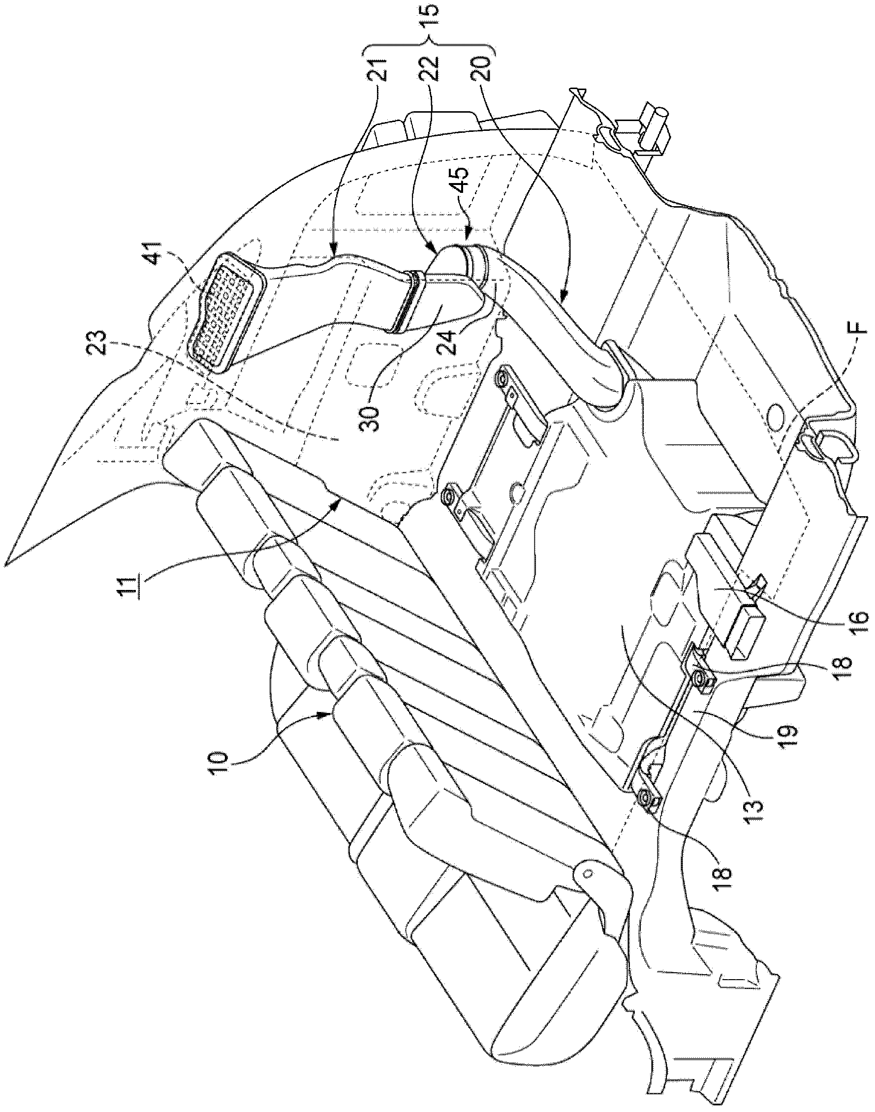
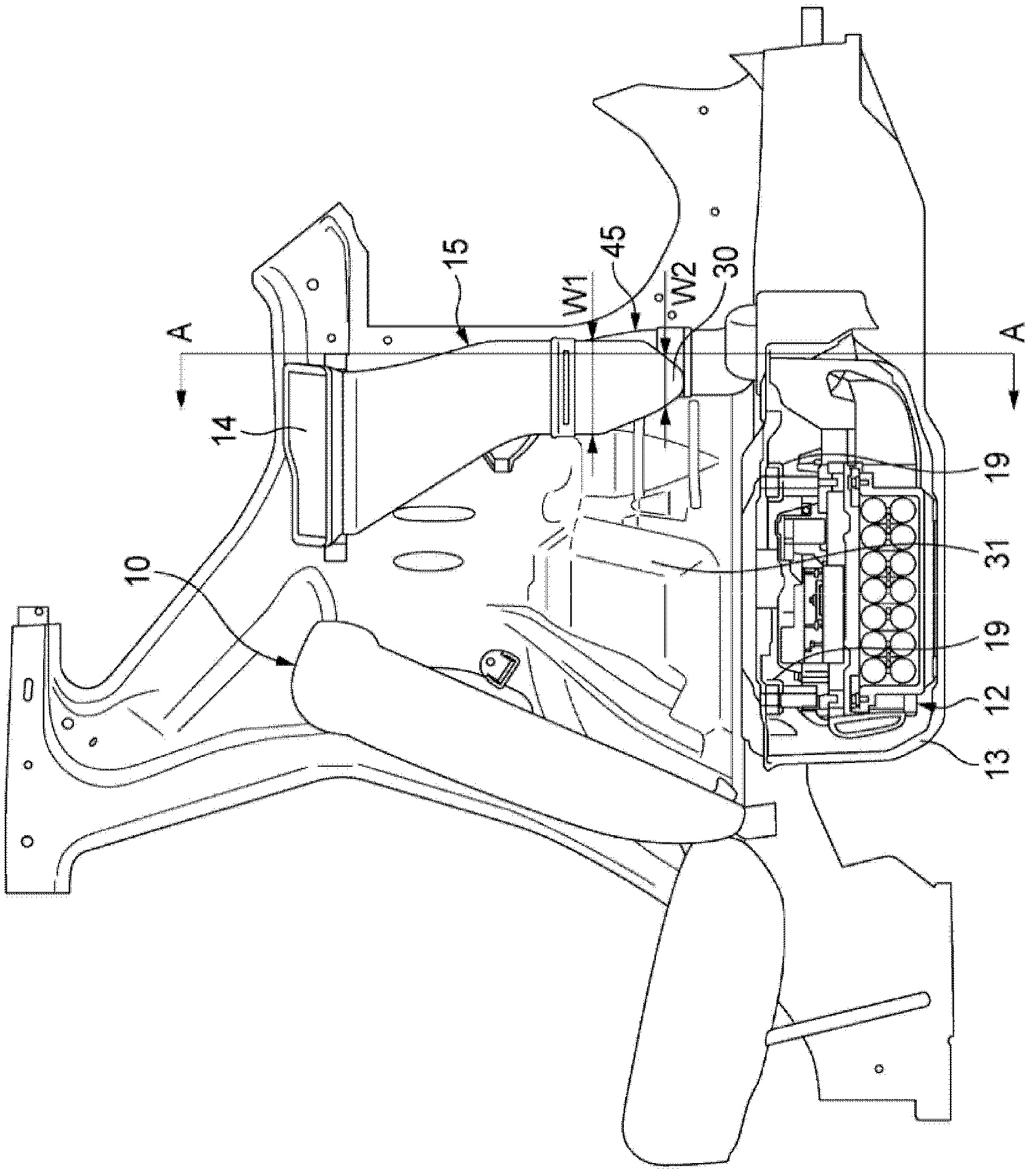
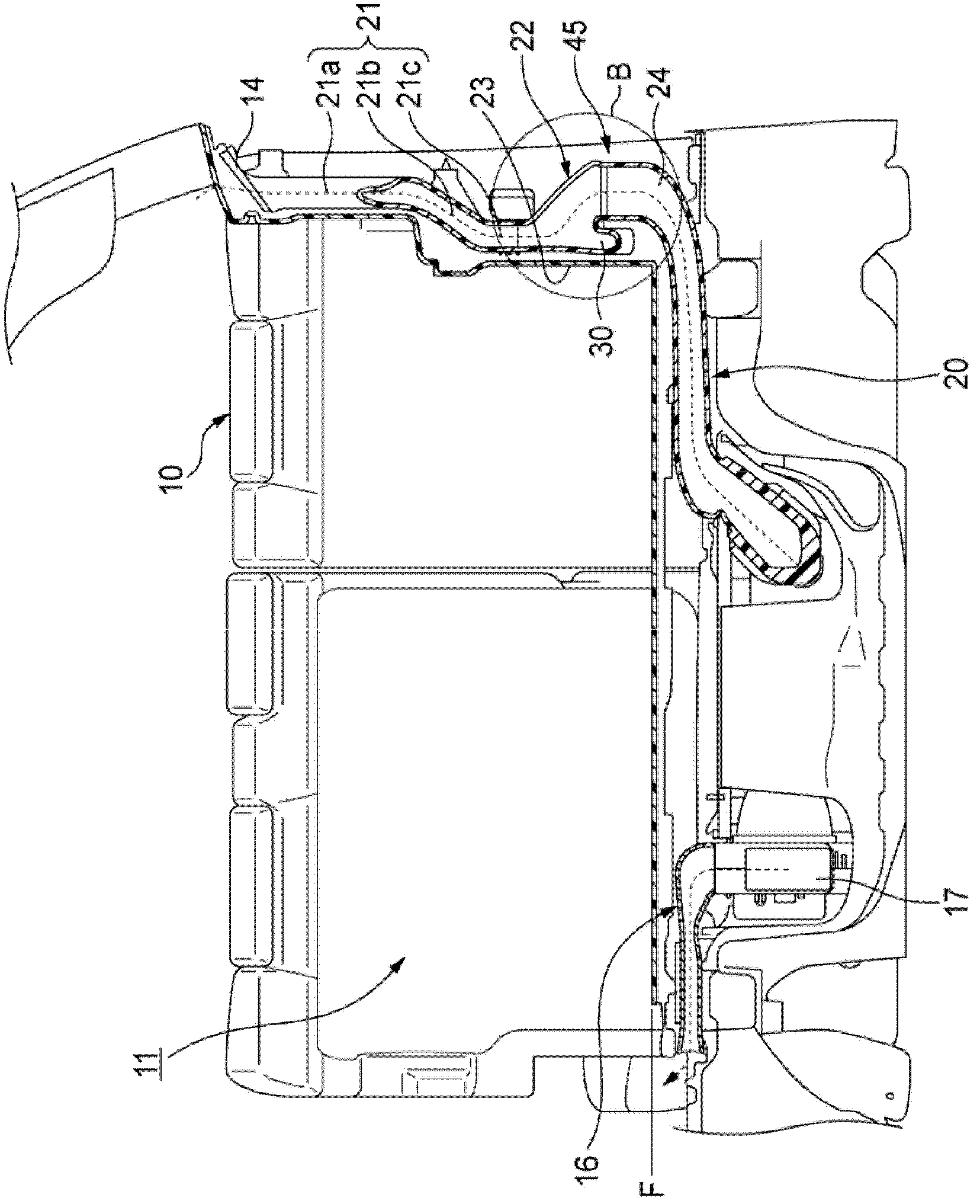
[0065] Such as Figure 1 ~ Figure 4 As shown, the vehicle battery cooling structure of this embodiment includes: a battery 12 disposed under the floor of the luggage room 11 behind the rear seat 10, and the battery 12 is accommodated in a waterproof case 13; an air intake duct 15, which has an air inlet 14, and one end on the downstream side of the air inlet duct 15 is connected to the waterproof casing 13, and the air inlet duct 15 supplies the air introduced from the air inlet 14 to the battery 12 as cooling air; The air duct 16 has an upstream end connected to the waterproof case 13 , and the exhaust duct 16 discharges the cooling air that has cooled the battery 12 from the waterproof case 13 . In addition, reference numeral F denotes the floor surface of the luggage room 11 .

[0066] The...


PUM


Abstract

The invention provides a cooling mechanism of a vehicle battery, which can inhibit pressure loss caused by air supply and can ensure a spacious space. An air inlet pipeline (15) comprises a first pipeline component (20), at least a part of which is disposed under a floor, an upstream side second pipeline component (21) and a downstream side second pipeline component (22), which are disposed at a position other than below the floor. A connection part (45) of the first pipeline component (20) and the downstream side second pipeline component (22) is disposed at a position other than below the floor.

Description

technical field [0001] The present invention relates to a cooling structure suitable for batteries used in vehicles such as electric vehicles and hybrid vehicles. Background technique [0002] In an electric vehicle or a hybrid vehicle, for example, a battery serving as a driving energy source for a motor is mounted under a floor of a luggage space. The battery is a heat-generating component that generates heat during charging and discharging, so it needs to be cooled to maintain battery performance, and cooling by cooling air drawn from the interior of the vehicle, etc., has been studied (for example, refer to Patent Document 1). [0003] The cooling structure of the power supply unit for a vehicle described in Patent Document 1 is such that the air in the cabin is drawn in by a cooling fan from an air intake provided near the rear seat, and the air is supplied as cooling air to the power supply unit including the battery. Allow to cool. The power supply unit accommodated...

Claims


Application Information

Patent Timeline
Patent Type & Authority Patents(China)
IPC IPC(8): B60K11/06H01M10/613H01M10/625B60K1/04B60L11/18B62D25/20H01M2/10H01M10/60H01M10/6563
CPCY02T10/7005Y02E60/10Y02T10/70
Inventor 平西亨西堀毅雄
Owner HONDA MOTOR CO LTD
Why Eureka
Try Eureka