

Measuring method of remote transmission rate
A technology for measuring methods and rates, applied in transmission systems, digital transmission systems, electrical components, etc.
Active Publication Date: 2018-08-28
CNPC GREATWALL DRILLING ENG
View PDF2 Cites 0 Cited by
- Summary
- Abstract
- Description
- Claims
- Application Information
AI Technical Summary
Problems solved by technology
[0004] The purpose of the present invention is to solve the problem of numerical determination of the remote transmission rate performance in the development, measurement and production of the remote transmission system, and to provide a method for measuring the remote transmission rate that can automatically and quickly determine the remote transmission rate
Method used
View moreImage
Smart ImageViewing Examples

Examples
Embodiment
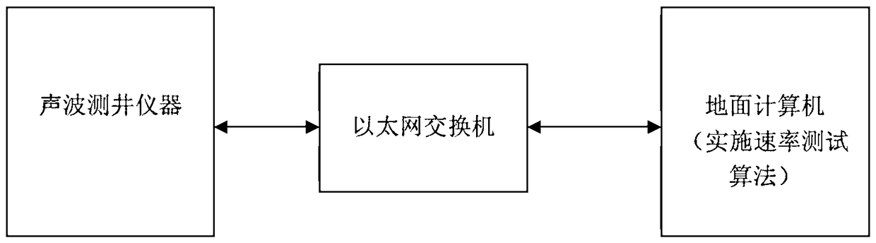
[0058] Figure 4 An embodiment of the method for measuring the telemetry rate of the present invention is shown, which is composed of a ground computer, an Ethernet switch, and an acoustic logging instrument. The computer software on the surface is executed to control the sonic well logging instrument, thereby executing the rate measurement method of the present invention. The computer controls the sonic logging tool through the Ethernet switch, and can automatically and quickly measure the remote transmission rate from the sonic logging tool to the surface computer.
Login to View More PUM
 Abstract
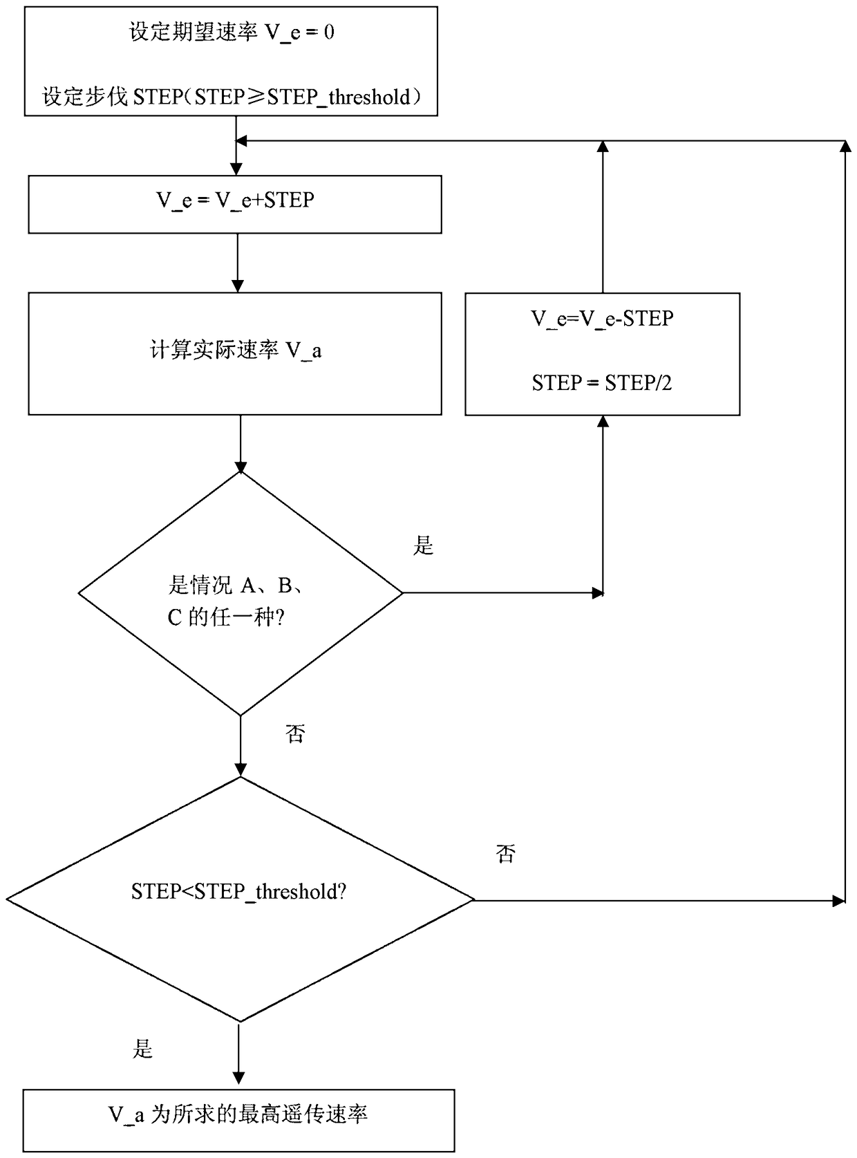
The invention relates to a telemetry speed measuring method, which is used for measuring a telemetry speed, wherein a computer is used for setting a message generation speed of analog equipment and measuring the maximum speed of a message sent by the analog equipment. The telemetry speed measuring method comprises the following steps of: 1, setting an initial value of an expected speed and an initial value of a speed increase pace, wherein the speed increase pace is more than or equal to the regulated pace threshold; 2, enabling the expected speed to increase according to the pace; 3, calculating an actual speed; 4, judging whether to execute a step 5 or adjust the pace and the expected speed according to whether any one of the following conditions, namely, (A) packet loss is discovered, (B) the error between the actual speed and the expected speed is larger than the preset error threshold and (C) the actual speed is lower than the actual speed before the expected speed is increased most recently, happens; and 5, judging whether to execute the step 2 according to the relationship between the amplitude and the regulated amplitude threshold. According to the telemetry speed measuring method disclosed by the invention, the telemetry speed can be automatically and rapidly measured.
Description
technical field [0001] The invention relates to a method for measuring the remote transmission rate, in particular to a method for measuring the remote transmission rate of a well logging system. Background technique [0002] Well logging, also known as geophysical well logging or petroleum well logging, referred to as well logging, is a method of measuring geophysical parameters using the electrochemical properties, electrical conductivity, acoustic properties, radioactivity and other geophysical properties of rock formations, which belongs to applied geophysical methods (Including gravity, magnetic, electric, seismic, logging). Generally, according to the detected rock physical properties or detection purposes, it can be divided into electrical logging, acoustic logging, radioactive logging, formation dip logging, gas logging, formation determination logging, gas drilling logging, etc. During the well logging process, various logging instruments manufactured using physica...
Claims
Login to View More Application Information
Patent Timeline
 Patent Type & Authority Patents(China)
IPC IPC(8): H04L12/26
Inventor 岳宏图陈文轩裴彬彬孙云涛戴光明朱新楷
Owner CNPC GREATWALL DRILLING ENG