Integrated thermal cycling system of electric vehicle
What is Al technical title?
Al technical title is built by PatSnap Al team. It summarizes the technical point description of the patent document.
A technology of circulation system and electric vehicle, which is applied in the layout, circuit, and electrical components of the power plant's cooling combination. Consistency and other issues to achieve the effect of satisfying cooling and heating, improving overall efficiency, and improving life and efficiency
Active Publication Date: 2013-02-27
SAIC MOTOR
View PDF4 Cites 151 Cited by
Summary
Abstract
Description
Claims
Application Information
AI Technical Summary
This helps you quickly interpret patents by identifying the three key elements:
Problems solved by technology
Method used
Benefits of technology
Problems solved by technology
[0002] At present, the air-conditioning system, power battery thermal management system, and motor system thermal management system of electric vehicles on the market are generally independent, and there are few systems that integrate the heat dissipation and heating system of the battery pack, the air-conditioning refrigeration system, the heating system, and the cooling of the motor. The systems are integrated together, which results in low efficiency of the vehicle thermal management system and fails to achieve the maximum utilization rate of the vehicle thermal environment resources
And the power battery generally adopts a simple air-cooled system, and rarely uses a water-cooled system. In this way, in a hot or cold environment, it is difficult to guarantee the optimal working temperature of the power battery, and it is also impossible to ensure the consistency of the temperature between the batteries, thereby reducing the battery life. life and charge-discharge performance
Method used
Image
Click on the blue label to locate the original text in one second.
Reading with bidirectional positioning of images and text.
Examples
Embodiment 1
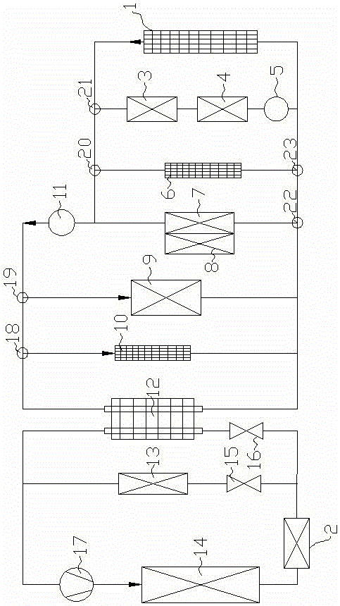
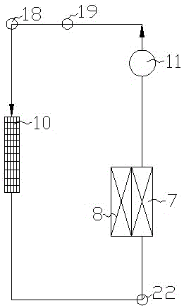
[0028] like figure 1 As shown, a comprehensive thermal cycle system for electric vehicles includes a motor system radiator 1, a motor 3, a motor controller 4, an air conditioning system, a first water pump 5, a heater 6, a water cooling jacket 7, a battery pack 8, and a heater 9. The battery pack radiator 10, the second water pump 11, the heat exchanger 12 and the evaporator 13; the heat exchanger 12 is connected with a refrigerant pipeline and a water pipeline, and the water cooling jacket 7 is installed on the battery pack 8 , the motor system radiator 1, the first water pump 5, the motor controller 4, and the motor 3 that are connected sequentially according to the circulating water flow form a motor cooling cycle;
[0029] The refrigerant pipeline of the heat exchanger 12 is connected in series with the second expansion valve 16, the evaporator 13 is connected in series with the first expansion valve 15, the first expansion valve 15 and the second expansion valve 16 are co...
PUM
Abstract
The invention relates to the field of heat management of electric vehicles, and in particular to an integrated thermal cycling system of an electric vehicle. The integrated thermal cycling system of the electric vehicle comprises a motor system heat dissipation device, a motor, a motor controller, an air-conditioning system, a first water pump, an air heater, a water cooling jacket, a battery pack, a heater, a battery pack heat dissipation device, a second water pump, a heat exchanger and an evaporator; and a refrigerant pipeline and a water pipeline are connected onto the heat exchanger, the water cooling jacket is installed on the battery pack, and the motor system heat dissipation device, the first water pump, the motor controller and a motor are sequentially and circularly connected with each other according to the circulating water flowing direction, so that a motor cooling cycling circuit is formed. When the environment temperature is low, the battery pack is preheated and heated and an air conditioner in the vehicle is warmed up before the electric vehicle is started, when the environment temperature is high, the battery pack is cooled, a cab is refrigerated and the motor and the motor controller are cooled, accordingly, high requirements on the self operating temperatures of the motor system and a battery are satisfied, so that the service lives and efficiency of the motor system and the battery are increased.
Description
technical field [0001] The invention relates to the field of thermal management of electric vehicles, in particular to a thermal cycle system of electric vehicles. Background technique [0002] At present, the air-conditioning system, power battery thermal management system, and motor system thermal management system of electric vehicles on the market are generally independent, and few of them have integrated the heat dissipation and heating system of the battery pack, the air-conditioning refrigeration system, the heating system, and the cooling of the motor. The systems are integrated together, which results in low efficiency of the vehicle thermal management system and fails to achieve the maximum utilization rate of the vehicle thermal environment resources. And the power battery generally adopts a simple air-cooled system, and rarely uses a water-cooled system. In this way, in a hot or cold environment, it is difficult to guarantee the optimal working temperature of the...
Claims
Application Information
Patent Timeline
Application Date:The date an application was filed.
Publication Date:The date a patent or application was officially published.
First Publication Date:The earliest publication date of a patent with the same application number.
Issue Date:Publication date of the patent grant document.
PCT Entry Date:The Entry date of PCT National Phase.
Estimated Expiry Date:The statutory expiry date of a patent right according to the Patent Law, and it is the longest term of protection that the patent right can achieve without the termination of the patent right due to other reasons(Term extension factor has been taken into account ).
Invalid Date:Actual expiry date is based on effective date or publication date of legal transaction data of invalid patent.