Phase-calibrated 3D-package surface antenna with embedded plated through holes

A technology of metallized vias and three-dimensional packaging, which is applied to the structural form of radiation elements, circuits, waveguide horns, etc., can solve the problems of radiation directivity and gain reduction, phase asynchrony, and uneven phase distribution of aperture electric field intensity, etc., to achieve Improve the aperture efficiency and gain, the effect of uniform phase distribution

Inactive Publication Date: 2013-04-03
SOUTHEAST UNIV
View PDF3 Cites 1 Cited by
  • Summary
  • Abstract
  • Description
  • Claims
  • Application Information

AI Technical Summary

Problems solved by technology

However, the horn antenna is usually non-planar, incompatible with the planar circuit process, and has a large geometric size, which limits its application in the packaging structure
In recent years, the substrate-integrated waveguide horn antenna developed based on substrate-integrated waveguide technology has the characteristics of small size, light weight, and easy planar integration, but the gain of the traditional substrate-integrated waveguide horn antenna is relatively low. The reason is that the horn The continuous opening of the mouth causes the phase out of synchronization when the electromagnetic wave propagates to the horn's aperture surface, the phase distribution of the electric field intensity of the aperture is uneven, and the radiation directivity and gain decrease
At present, methods such as dielectric loading and dielectric prisms have been used to correct the phase of the horn aperture field, but these phase calibration structures increase the overall structural size of the antenna and are not suitable for integration into the package surface

Method used


Image

  • Phase-calibrated 3D-package surface antenna with embedded plated through holes
  • Phase-calibrated 3D-package surface antenna with embedded plated through holes
  • Phase-calibrated 3D-package surface antenna with embedded plated through holes

Examples


Embodiment Construction

[0020] The present invention will be further described below in conjunction with drawings and embodiments.

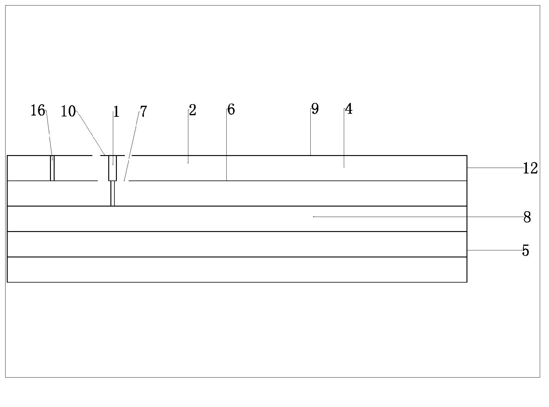
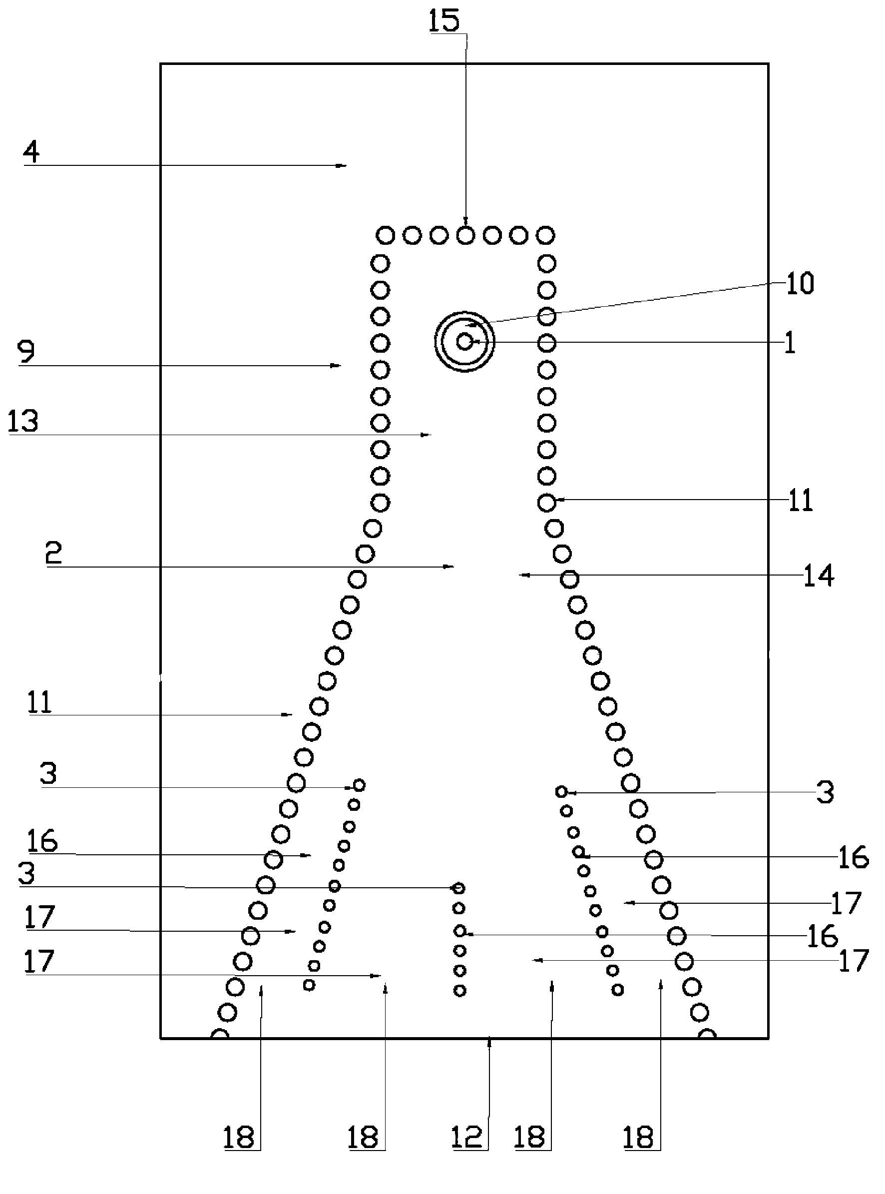
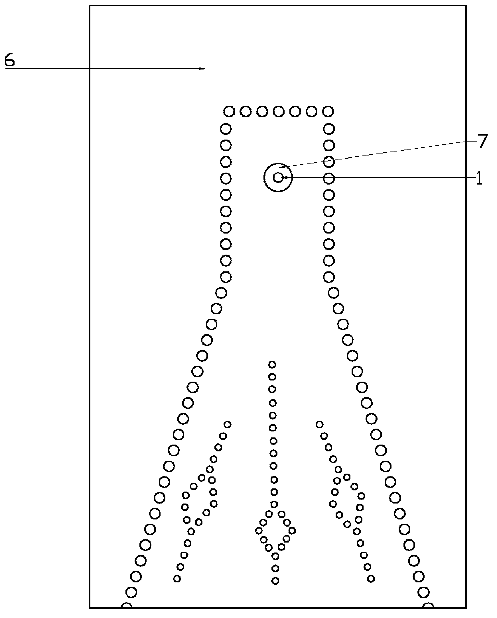
[0021] The implementation scheme adopted by the present invention is: the three-dimensional package surface antenna embedded with metallized vias for phase calibration is composed of three parts: metallized vertical via hole feeder 1, substrate integrated waveguide horn antenna 2 and embedded metallized vias 3. These three parts are all integrated on the same dielectric substrate 4, and the dielectric substrate 4 is on the top of the three-dimensional package 5; the metallized vertical via hole feeder 1 vertically penetrates the dielectric substrate 4, and one end of the metallized vertical via hole feeder 1 passes through the dielectric substrate 4. The round hole 7 on the bottom metal plane 6 is connected to the internal circuit 8 of the three-dimensional package 5, and is the input and output port of the antenna. There is a round pad 10 on the top of the other end of ...


PUM


Abstract

The invention relates to a horn antenna, in particular to a phase-calibrated 3D-package surface antenna with embedded plated through holes. The antenna comprises a plated vertical through hole feeder (1), a horn antenna (2) and plated through holes (3), wherein the plated vertical through hole feeder (1), the horn antenna (2) and the plated through holes (3) are integrated on a dielectric substrate (4). The dielectric substrate (4) is arranged at the topmost of 3D package (5). One end of the plated vertical through hole feeder (1) is connected with an internal circuit (8). The horn antenna (2) comprises a bottom metal plane (6), a top metal plane (9) and plated through hole sidewalls (11). Through hole arrays (16) of the plated through holes (3) form a plurality of dielectric loaded waveguides (17) in the horn antenna (2). One port of each dielectric loaded waveguide (17) faces to a short surface (15) of a narrow-section waveguide (13), and the other port (18) of each dielectric loaded waveguide (17) extends towards an antenna aperture surface (12) without reaching the same. Gain of the phase-calibrated 3D-package surface antenna with embedded plated through holes can be increased.

Description

technical field [0001] The invention relates to a horn antenna, in particular to a three-dimensional packaged surface antenna embedded with metallized via holes for phase calibration. Background technique [0002] Using micro-assembly technology, a radio frequency system can be integrated in a package, for which the antenna also needs to be integrated on the surface of the package. It is a natural way to integrate a patch antenna on the surface of the package, but the main radiation direction of the patch antenna is the normal direction of the surface, and the main radiation direction we sometimes need is along the surface direction. If the horn antenna is integrated on the surface of the package, the radiation along the surface direction can be realized. However, horn antennas are usually non-planar, incompatible with planar circuit technology, and have large geometric dimensions, which limits their application in packaging structures. In recent years, the substrate-integ...

Claims


Application Information

Patent Timeline
Patent Type & Authority Applications(China)
IPC IPC(8): H01Q1/38H01Q13/02
Inventor 赵洪新殷晓星王磊
Owner SOUTHEAST UNIV
Why Eureka
Try Eureka