Sensor power supply method and device

A power supply method and sensor technology, applied in circuit devices, battery circuit devices, transportation and packaging, etc., can solve problems such as no solutions, and achieve the effect of eliminating stray currents

Active Publication Date: 2015-10-07
北京碧海云智新材料技术有限公司
View PDF2 Cites 0 Cited by
  • Summary
  • Abstract
  • Description
  • Claims
  • Application Information

AI Technical Summary

Problems solved by technology

[0005] For the above problems, no effective solution has been proposed

Method used


Image

  • Sensor power supply method and device
  • Sensor power supply method and device
  • Sensor power supply method and device

Examples


Embodiment Construction

[0024] Hereinafter, the present invention will be described in detail with reference to the drawings and examples. It should be noted that, in the case of no conflict, the embodiments in the present application and the features in the embodiments can be combined with each other.

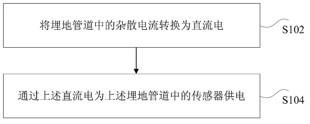
[0025] The embodiment of the present invention provides a preferred sensor power supply method, such as figure 1 As shown, the method includes the following steps:

[0026] Step S102: converting the stray current in the buried pipeline into direct current;

[0027] Step S104: providing power to the sensors in the buried pipeline through the direct current.

[0028] In the above preferred embodiment, the stray current in the buried pipeline is used as the power supply of the sensor in the buried pipeline, which solves the technical problem that it is difficult to supply power to the sensor in the prior art, and achieves The technical effect of powering the sensor.

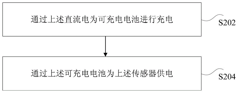
[0029] Considering that if the ...


PUM


Abstract

The invention discloses a method and a device for sensor power supply. The method comprises converting stray current in a buried pipeline to direct current and supplying electric power to a sensor in the buried pipeline through the direct current. The method and the device for the sensor power supply solve the technical problem that supplying electric power to the sensor is difficult in the prior art so that the technical effects that the stray current is eliminated and the electric power is supplied to the sensor are achieved.

Description

technical field [0001] The invention relates to the electrical field, in particular to a sensor power supply method and device. Background technique [0002] With the development of long-distance transmission pipelines, power transmission and transformation lines, and electrified railways, there are more and more cases where the three share public corridors, cross, and approach each other. At the same time, due to the recent large-scale construction of buried oil and gas pipelines, three-layer polyethylene (PE for short), epoxy powder and other high-insulation resistivity anti-corrosion coatings are mainly used, which will cause AC or DC stray current interference affects the safe operation of pipelines. Therefore, there is a need to eliminate stray currents in buried pipelines. [0003] At present, the commonly used methods to eliminate the interference of stray currents in buried steel pipelines mainly include: sacrificial anode technology, grounding system + AC decouple...

Claims


Application Information

Patent Timeline
Patent Type & Authority Patents(China)
IPC IPC(8): H02J7/00H02J17/00H02J50/00
Inventor 刘严强邸建军赖广森丁宝峰庄树才
Owner 北京碧海云智新材料技术有限公司
Why Eureka
Try Eureka