

Transmission input shaft damper
A technology for input shafts and transmissions, applied to elements with teeth, springs/shock absorbers, gear transmissions, etc., which can solve the problems of installation location or its space limitation, ISD volume increase, etc.
- Summary
- Abstract
- Description
- Claims
- Application Information
AI Technical Summary
Problems solved by technology
Method used
Image

Examples
Embodiment Construction
[0019] Reference hereafter will be made in detail to various embodiments of the invention, examples of which are shown in the accompanying drawings and described below. While the invention has been described in connection with the preferred embodiments, it will be understood that present description is not intended to limit the invention to those preferred embodiments. On the contrary, the invention is intended to cover not only the preferred embodiments, but also various alternatives, modifications, equivalents and other embodiments, which may be included within the spirit and scope of the invention as defined by the appended claims.
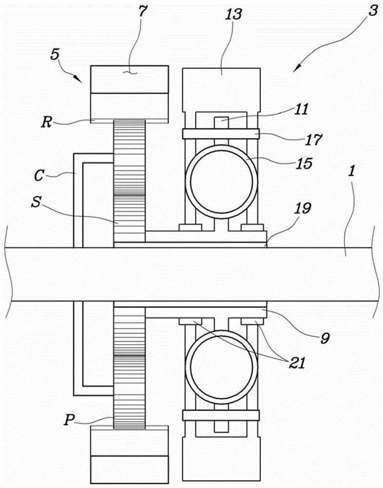
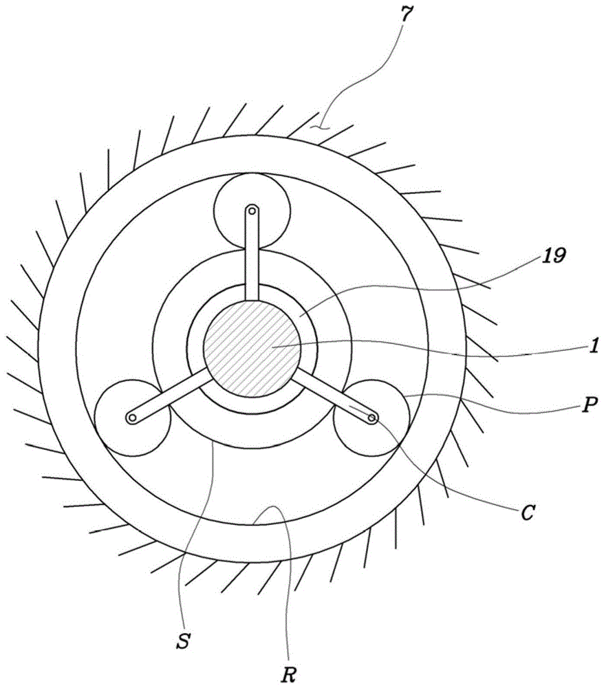
[0020] refer to figure 1 with 2 , the ISD according to the exemplary embodiment of the present invention is configured to include an inertial body assembly 3 relatively rotatably mounted on the input shaft 1 of the transmission; and a planetary gear set 5, the planetary gear A group 5 is installed on the input shaft 1 to receive and increase...
PUM
 Abstract
Description
Claims
Application Information