Compressors with variable compressor inlet

一种压缩机、压缩机壳体的技术,应用在机器/发动机、机械设备、非变容式泵等方向

Inactive Publication Date: 2017-05-03
CONTINENTAL AUTOMOTIVE GMBH
View PDF2 Cites 0 Cited by
  • Summary
  • Abstract
  • Description
  • Claims
  • Application Information

AI Technical Summary

Problems solved by technology

Here, the key would be that there is not enough mounting space available for this device and there are robustness issues with regard to cycle times and temperature loads

Method used


Image

  • Compressors with variable compressor inlet

Examples


Embodiment Construction

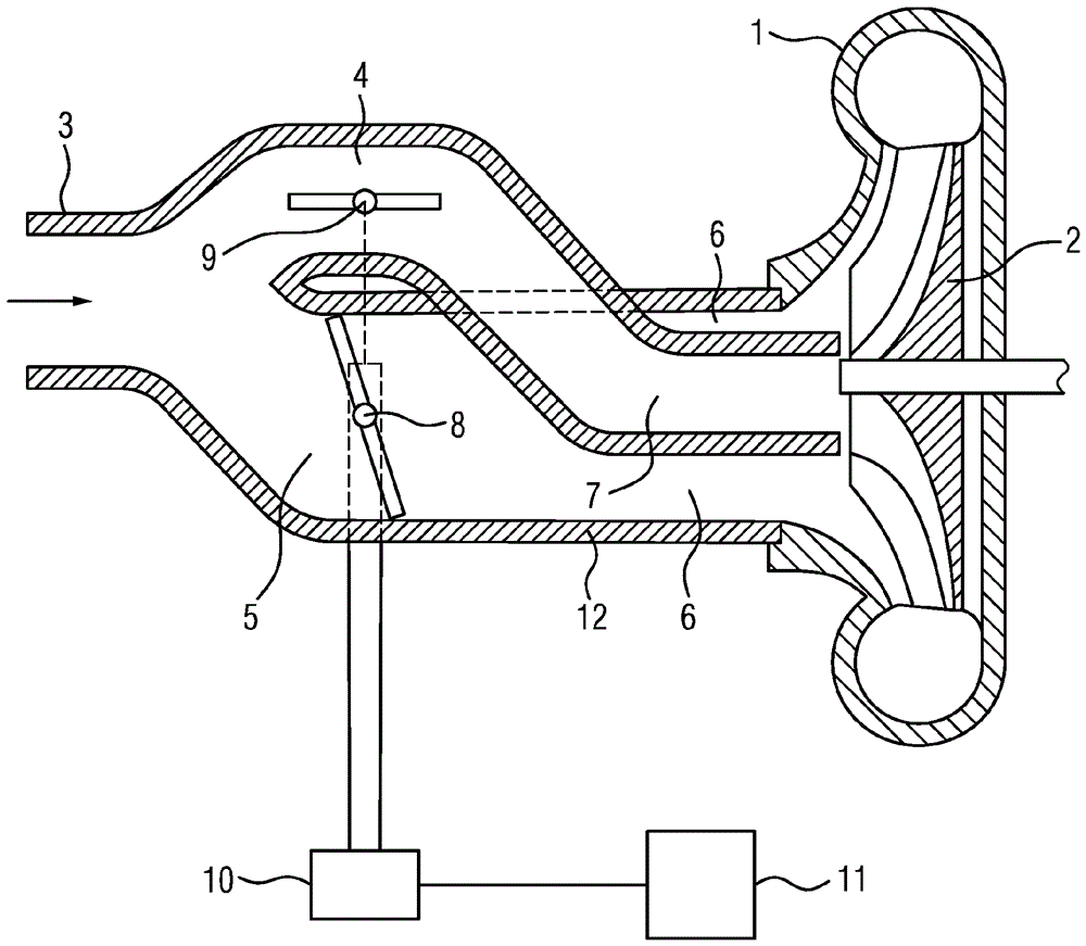
[0020] In the corresponding schematic cross-sectional illustration, a compressor housing 1 with an associated compressor inlet 12 is shown. A compressor wheel 2 with corresponding compressor blades (indicated only schematically) is located in the compressor housing 1. The air flows out from the intake filter (not shown) and flows into the header 3, and from there into the compressor inlet 12. Adjacent to the header 3, the compressor inlet 12 has two separate tubes 4, 5 arranged adjacent to each other into which the header 3 merges. The upper pipe 4 shown in the figure extends into the lower pipe 5 and thus forms two concentric pipes (ie, the inner pipe 7 and the outer pipe 6) and is adjacent to the compressor housing 1 in the area of ​​the compressor inlet 12. In this case, the inner pipe 7 is directed toward the radially inner area, and the outer pipe 6 is directed toward the radially outer area of ​​the compressor blades. In terms of cross section, the inner tube 7 has a ci...


PUM


Abstract

A compressor for a turbocharger is described having: a compressor housing; a compressor wheel having compressor blades mounted therein; and a compressor inlet. The compressor inlet includes, at least in a section adjacent to the compressor housing, an inner tube and an outer tube surrounding the inner tube. The inner tube is directed towards a radially inner region of the compressor blade, and the outer tube is directed towards a radially outer region of the compressor blade. The passage section of the outer tube and / or the inner tube can be at least partially closed such that the compressor blades can be exposed to the variable flow. Therefore, the approach flow to the compressor is optimized according to the engine load.

Description

Technical field [0001] The present invention relates to a compressor of a turbocharger (in particular, an exhaust-gas turbocharger), which has: a compressor housing; a compressor wheel having compressor blades installed therein; and a compressor inlet, wherein The compressor inlet includes an inner pipe and an outer pipe surrounding the inner pipe at least in a section adjacent to the compressor housing, the inner pipe being directed toward the radially inner area of ​​the compressor blades, and The passage section of the outer tube and / or the inner tube can be at least partially closed by means of a closing device. Background technique [0002] Due to the optimization of spark-ignition engines and its goal is to reduce consumption, the requirements for the working range of the turbocharger are increasing day by day. The most important reason for this is that when the engine is under partial load, the engine runs at the lowest possible speed but at high torque to improve efficie...

Claims


Application Information

Patent Timeline
Patent Type & Authority Patents(China)
IPC IPC(8): F04D27/02F04D29/42
CPCF04D27/0253F04D29/4213F05D2250/51F05D2220/40F02D41/0007F04D27/003F04D29/4206
Inventor M.魏格尔P.格拉斯
Owner CONTINENTAL AUTOMOTIVE GMBH
Why Eureka
Try Eureka