A light-emitting device and its preparation method

A technology of light-emitting components and substrates, applied in chemical instruments and methods, light-emitting materials, electrical components, etc., can solve the problems of low luminous efficiency, achieve enhanced luminous efficiency, enhanced spontaneous radiation, and simple process preparation

Inactive Publication Date: 2015-11-25
OCEANS KING LIGHTING SCI&TECH CO LTD
View PDF5 Cites 0 Cited by
  • Summary
  • Abstract
  • Description
  • Claims
  • Application Information

AI Technical Summary

Problems solved by technology

[0004] However, when transparent ceramics are used as luminescent materials in field emission devices, they have the problem of low luminous efficiency

Method used


Image

  • A light-emitting device and its preparation method
  • A light-emitting device and its preparation method
  • A light-emitting device and its preparation method

Examples


preparation example Construction

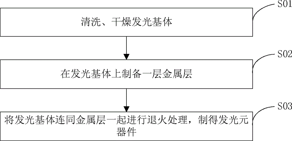
[0023] The present invention also provides a method for preparing the above-mentioned light-emitting components, such as figure 2 As shown, its preparation process includes:

[0024] S01. Clean the luminescent substrate in acetone, deionized water, and absolute ethanol in sequence, and then dry or blow dry;

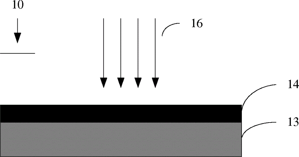
[0025] S02. Prepare a metal layer on the surface of the light-emitting substrate;

[0026] S03, performing annealing treatment on the light-emitting substrate prepared with the metal layer in a vacuum state, and after cooling, a light-emitting device containing a metal microstructure in the metal layer is prepared.

[0027] In step S01 of the above-mentioned preparation method, the light-emitting matrix adopts Eu-doped Y 2 o 3 System transparent luminescent ceramics, its chemical composition is Y 2 o 3 : Eu; In the process of use, the transparent ceramic needs to be machined, polished, etc. to make shapes that meet the needs of various applications, that is, the lum...

Embodiment 1

[0040] Y doped with Eu 2 o 3 System transparent ceramic sheet, that is, the chemical composition is Y 2 o 3 : Eu luminescent ceramics as a luminescent substrate, and then use magnetron sputtering equipment to deposit a metal silver layer with a thickness of 20 nanometers on the transparent ceramic surface, and then place it in a vacuum of less than 1×10 -3 Under the vacuum environment of Pa, annealing at 300° C. for half an hour, and then cooling to room temperature, a light-emitting element having a metal layer with a metal microstructure is obtained.

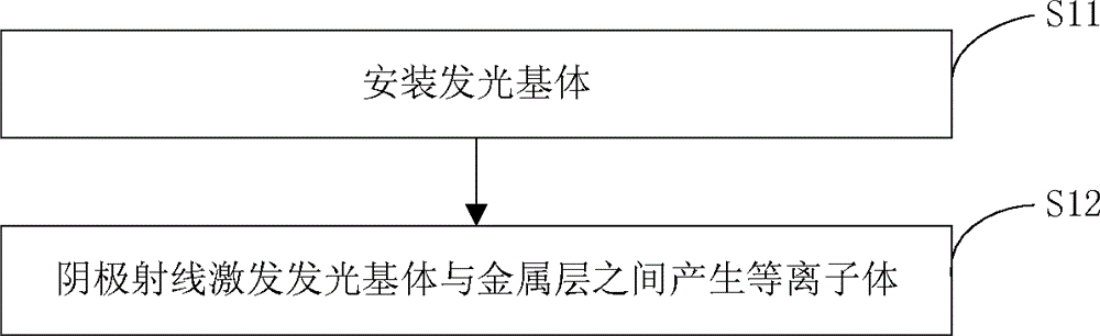
[0041] Spectral test is carried out on the light-emitting element prepared above, and the cathode ray generated by the electron gun is used to bombard the light-emitting element, and the electron beam first penetrates the metal layer and then excites Y 2 o 3 : Eu transparent ceramics emit light, producing such as Figure 4 The luminescent spectrum shown in the figure shows that the luminescent material is a green luminesc...

Embodiment 2

[0043] The difference between Example 2 and Example 1 is that a metal gold layer with a thickness of 200 nanometers is deposited on the surface of the luminescent substrate, and then it is placed in a vacuum with a degree of less than 1×10 -3 In a vacuum environment of Pa, annealing treatment was performed at a temperature of 650° C. for 1 hour, and then cooled to room temperature to obtain a light-emitting element with a metal layer with a metal microstructure.


PUM

PropertyMeasurementUnit
thicknessaaaaaaaaaa

Abstract

A light emitting device and a manufacturing method thereof are provided. The light emitting device (10) comprises a light emitting substrate (13) and a metal layer (14) having irregularly arranged nano-particles structure formed on a surface of the light emitting substrate (13), wherein the material of the light emitting substrate (13) is a transparent ceramic (13) comprised of Y 2 O 3 :Eu. By disposing the metal layer having the irregularly arranged nano-particles structure on the light emitting substrate, surface Plasmon is formed on the interface between the cathode ray and the light emitting substrate, to greatly increase the light efficiency.

Description

technical field [0001] The invention relates to the field of luminescent materials, in particular to a luminescent component. The invention also relates to a preparation method of the light-emitting component. Background technique [0002] Traditional materials used as luminescent substrates include phosphors, nanocrystals, luminescent glass, and transparent ceramics. Compared with other luminescent materials, transparent ceramics have unique advantages. Compared with luminescent glass, transparent ceramics have higher luminous efficiency; compared with phosphors and nanocrystals, transparent ceramics have transparency, high mechanical strength, and chemical stability. Good performance, and it is easier to be processed into products of various sizes and shapes, such as display devices or lighting sources of various shapes or sizes. [0003] For example, in the field of vacuum microelectronics, field emission devices usually use luminescent ceramics as illuminants, which ha...

Claims


Application Information

Patent Timeline
Patent Type & Authority Patents(China)
IPC IPC(8): H01L33/00H01J9/20H01J63/06
CPCH01L33/50C09K11/7774H01J29/20H01J29/28H01J31/127H01J63/04H01J63/06H01L33/005
Inventor 周明杰马文波刘玉刚
Owner OCEANS KING LIGHTING SCI&TECH CO LTD
Why Eureka
Try Eureka