Heat generating element

A technology of heat generation and components, applied in the field of heat generation components, can solve problems such as complex solutions

Active Publication Date: 2013-06-26
EBERSPACHER CATEM
View PDF12 Cites 10 Cited by
  • Summary
  • Abstract
  • Description
  • Claims
  • Application Information

AI Technical Summary

Problems solved by technology

[0006] This known previously proposed solution is relatively complex, since the s

Method used


Image

  • Heat generating element
  • Heat generating element
  • Heat generating element

Examples


Embodiment Construction

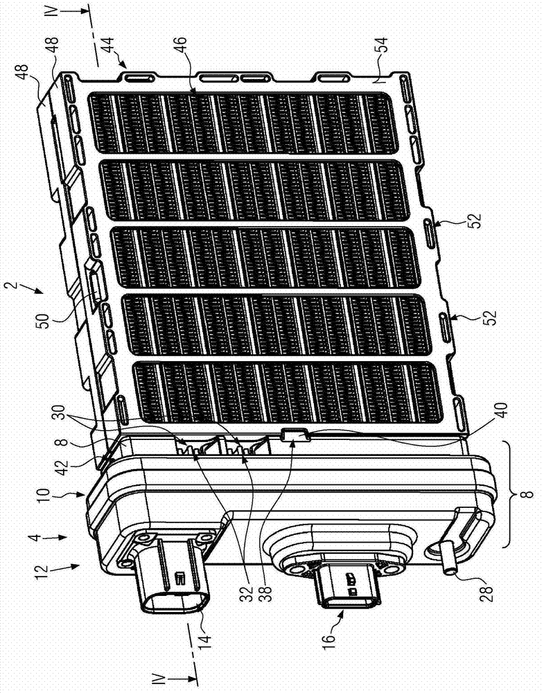
[0040] figure 1 An embodiment of an electric heating device is shown having a power part designated with reference numeral 2 and a control part designated with reference numeral 4 . The power part 2 and the control part 4 form a constructional unit of the electric heating device.

[0041] The control part 4 is formed externally by connecting the case 6, as in the Figure 4 Specifically shown in the diagram of the connection housing, the connection housing comprises a screening housing (screening housing) 8 (which is formed, for example, as a deep-drawn or cast metal housing respectively), a plastic housing element 10 (which is inserted into a metal housing 8) and housing cover 12. In the connected state, the housing cover 12 can be snapped onto the free flange of the sheet metal cup 8 and is made of metal so that the interior of the control part 4 is completely shielded by the metal connection housing 6 . However, the housing cover 12 can also be formed from plastic.

[00...


PUM


Abstract

The invention relates to a heat generating element, particularly to one for an electrical heating device for a motor vehicle. The heat generating element comprises a positional frame (76) and contact plates (82). The positional frame is formed in a way to make at least one PTC element (80) accommodated in receptacles (78). The contact plates abut oppositely situated sides of the PTC elements (80). Each receptacle 78 specified by a basically flat inner circumferential surface of the positional frame 76 has on oppositely situated sides at least two protrusions labelled with reference numeral 188.

Description

technical field [0001] The invention relates to a heat generating element, in particular for an electric heating device of a motor vehicle, having a position frame and a contact plate, the position frame being formed to accommodate at least one PTC element In the container therein, the contact plate adjoins two oppositely positioned sides of the PTC element. [0002] In particular, the invention relates to a heat generating element for an electric heating device of a motor vehicle, whereby the heating device has a frame forming openings on opposite sides for the passage of a medium to be heated. In the frame is arranged a layer structure that accommodates the above-mentioned heat generating elements, whereby in this layer structure, in each case, the corrugated rib elements generally adjoin in a thermally conductive manner oppositely positioned sides of the heat generating elements, so that the heat generating elements The heat generated by the heating element is regularly di...

Claims


Application Information

Patent Timeline
IPC IPC(8): H05B3/50F24H3/04F24H9/18
CPCF24H1/009F24H3/0405H04B3/50H05B3/286H05B2203/016H05B2203/02H05B2203/023B60H1/2225H05B3/50
Inventor 弗朗茨·博伦德米夏埃尔·尼德雷尔克里斯蒂安·摩根
Owner EBERSPACHER CATEM
Why Eureka
Try Eureka