a router

A router and free end technology, applied in the direction of digital transmission system, data exchange network, electrical components, etc., can solve the problems of increasing the feeder design of the electronic system, reducing the size of the wireless router, increasing the area of ​​the radio frequency system, etc., to achieve a good appearance, improve electromagnetic Effects of Signal Receiving and Transmitting Capability

Active Publication Date: 2018-09-14
KUANG CHI INST OF ADVANCED TECH
View PDF3 Cites 0 Cited by
  • Summary
  • Abstract
  • Description
  • Claims
  • Application Information

AI Technical Summary

Problems solved by technology

However, the impedance matching network additionally increases the feeder design of the electronic system and increases the area of ​​the radio frequency system. At the same time, the matching network also introduces a lot of energy loss, which is difficult to meet the system design requirements of low power consumption.
Therefore, the function and size of the antenna become the technical bottleneck for wireless routers to reduce the size and cost

Method used


Image

  • a router
  • a router
  • a router

Examples


Embodiment Construction

[0033] Reference will now be made in detail to the embodiments depicted in the accompanying drawings. In the following detailed description, numerous specific details are set forth in order to provide a thorough understanding of the present invention. However, it will be understood by those skilled in the art that the present invention may be practiced without these specific details. In other instances, well-known methods are not described in detail. procedures, components and circuits so as not to unnecessarily obscure the embodiments.

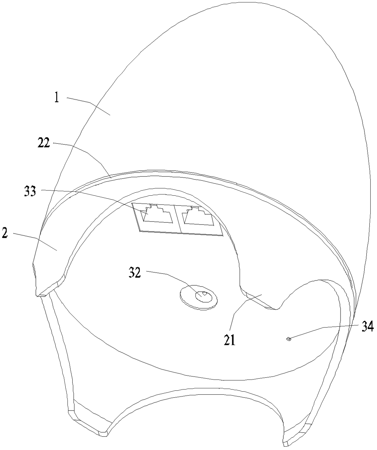
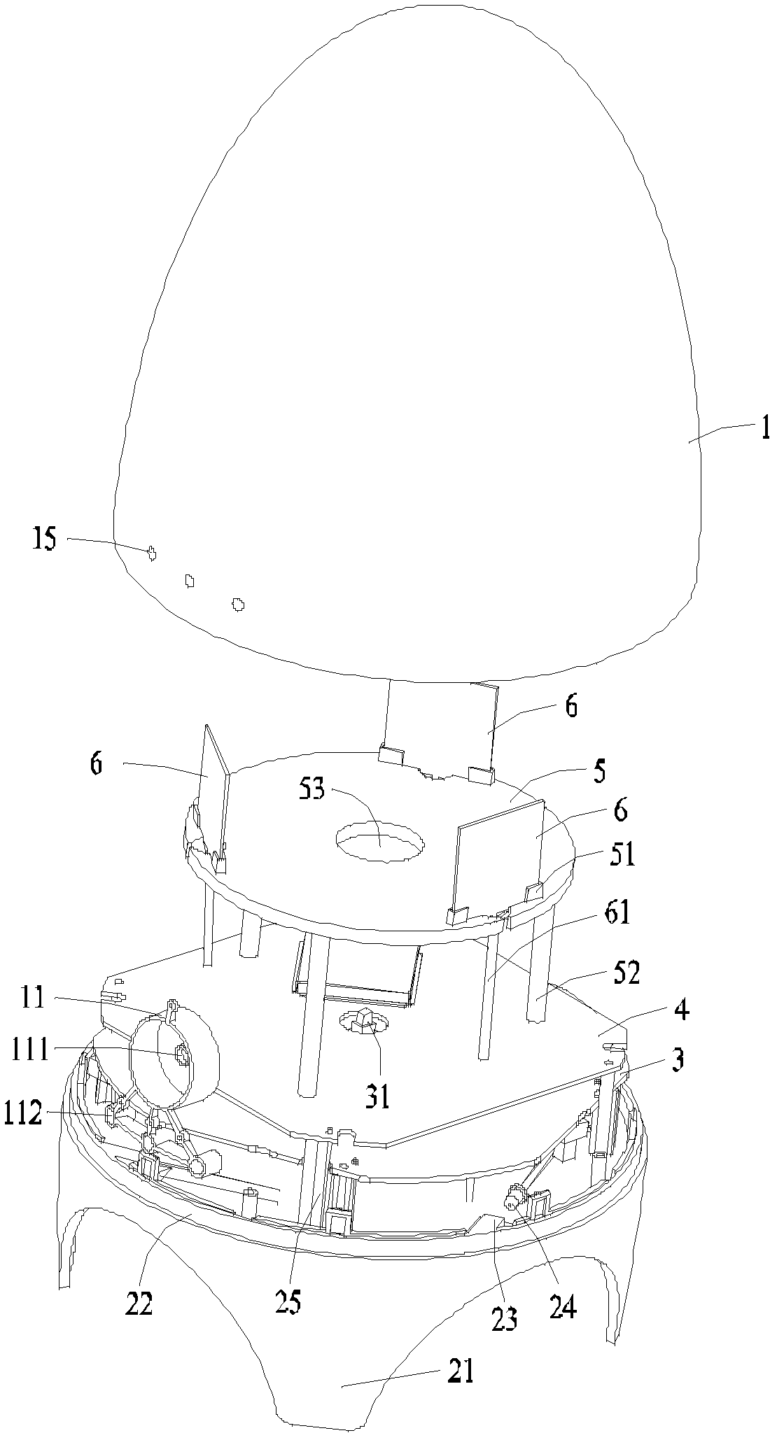
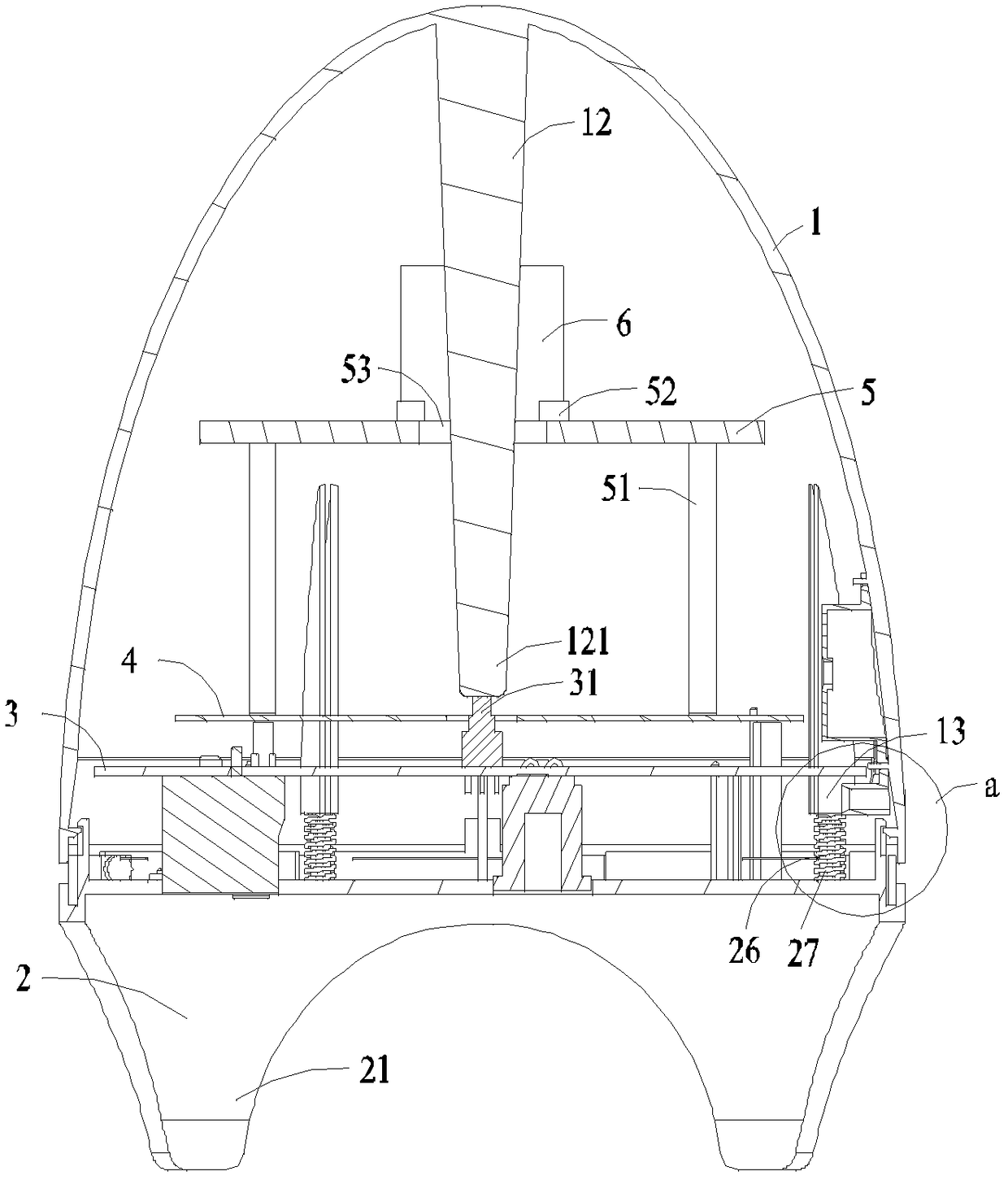
[0034] see figure 1 Shown is a schematic structural view of the router of the present invention, the router includes an upper shell 1 and a lower shell 2, wherein the upper shell 1 is in the shape of an ellipsoid, and may also be in the shape of a cuboid, cube, prism, etc., and the lower shell 2 includes a support portion 21 and The decorative part 22, in order to place the router stably, the lower case 2 is provided with four supporting p...


PUM


Abstract

The present invention provides a router, which includes a lower case, a PCB board, an upper case and a radiation part, wherein, the lower case is provided with a mounting base, a plurality of sets of columns fitted with springs, and a plurality of position-limiting parts located on the edge of the lower case; The board is installed on the mounting seat, and the sleeve column is arranged on the lower shell on the periphery of the PCB board; the upper shell includes a pressing part corresponding to the sleeve column, and a fastening part corresponding to the limit part; the pressing part is placed on the The free end of the spring and the fastening part are movably fastened to the limit part; the radiation part is electrically connected to the PCB board through a signal transmission line. The router of the present invention changes the traditional shape through structural design, solves the electromagnetic interference problem between the radiation unit, that is, the antenna and the PCB board, facilitates the built-in of the antenna, and has a good appearance; the unique design of the antenna improves the electromagnetic interference of the router. Signal receiving and sending capabilities can well meet the needs of wireless communication.

Description

technical field [0001] The invention belongs to the field of communication equipment, and in particular relates to a router. Background technique [0002] With the development of wireless communication technology, wireless communication equipment has higher and higher requirements. In order to meet the communication requirements, the existing wireless routers basically use external antennas, which greatly limits the industrial design and mechanism design of products. In addition, the external antenna also needs to design adaptive impedance matching connectors and mechanism modules. These connectors and mechanism modules account for more than 90% of the cost of the entire antenna, so the increase in the cost of the entire antenna has prompted the entire Rise in the price of wireless routers. [0003] Sometimes the data processing of the router limited to the antenna needs to install multiple antennas. The installation of multiple antennas outside the router casing not only a...

Claims


Application Information

Patent Timeline
Patent Type & Authority Patents(China)
IPC IPC(8): H04L12/771H01Q1/22H04L45/60
Inventor 刘若鹏徐冠雄吕晶李日照
Owner KUANG CHI INST OF ADVANCED TECH
Why Eureka
Try Eureka