Injection mould capable of being easily de-molded

A technology for injection molds and injection molds, which is applied in the field of molds, can solve problems such as the influence of replacement efficiency, substandard splines, and high labor intensity of operators, so as to meet the requirements of reducing operation proficiency, reduce mold costs, and improve mold change efficiency. Effect

Active Publication Date: 2013-10-23
广州现代塑料有限公司
View PDF6 Cites 3 Cited by
  • Summary
  • Abstract
  • Description
  • Claims
  • Application Information

AI Technical Summary

Problems solved by technology

[0005] ⑴. The injection molding process of various splines is different, and the existing molds gather all kinds of splines in the same mold, which cannot meet the injection molding process requirements of various splines at the same time, and it is easy to distort the quality of the test splines. Can not objectively and truly reflect the performance of the material
For example, stretching splines have certain requirements on the tendency of molecules, while relatively thick splines require a relatively long holding time to minimize the shrinkage of the splines, and injection molding requires fast The injection speed can fill the mold cavity. Obviously, no matter what injection molding process is used, it is impossible to meet the injection molding process requirements of all splines at the same time.
[0006] ⑵. Various splines of the same material need to test many performance indicators, and different materials have different test items in different periods, so it is impossible to produce standard splines that require all test indicators with the same mold.
[0008] ⑴. The mold is bulky and heavy, the assembly with the injection molding machine is complicated, and the labor intensity of the operator is very high, so that the whole process of changing the mold often takes about 45 minutes to an hour. Moreover, the specific conditions of the injection molding machine and the mold, the operator The physical fitness and operating proficiency of the operator will have an impact on the replacement efficiency, and directly affect the production efficiency of the spline
[0009] ⑵. Existing molds have relatively limited applicability to materials, and are only suitable for materials with moderate hardness. When the mold is opened to take out the spline, the ejection method is usually used, that is, several parts of the spline are selected as the ejection method. If the hardness of the spline material is high, it will be difficult to remove the mold due to the adhesion between the spline and the cavity wall of the mold. At this time, if the mold is forcibly removed, the performance of the spline will be affected. During the test, the spline is easy to break in the transition section between the clamping section and the working section; if the hardness of the spline material is low, the spline will be deformed after demolding, which is not conducive to the test of the performance index of the spline
The spline deformation mentioned above means that the spline produces a demoulding slope, that is, the cross-sectional shape of the spline is an inverted trapezoid with a large top and a small bottom. When calculating the tensile strength (MPa), it is necessary to calculate the area of ​​the cross-section For measurement, vernier calipers are generally used for measurement. However, vernier calipers can only measure the value of the top side (longer side), so the obtained cross-sectional area will be larger than the actual value, and the final tensile strength will be smaller than the actual data. The test data is inaccurate, and it is easy to cause the splines that are originally up to the standard to be measured as substandard splines. In this case, it is quite unfavorable to the manufacturer that provides the splines

Method used


Image

  • Injection mould capable of being easily de-molded
  • Injection mould capable of being easily de-molded
  • Injection mould capable of being easily de-molded

Examples


Embodiment 1

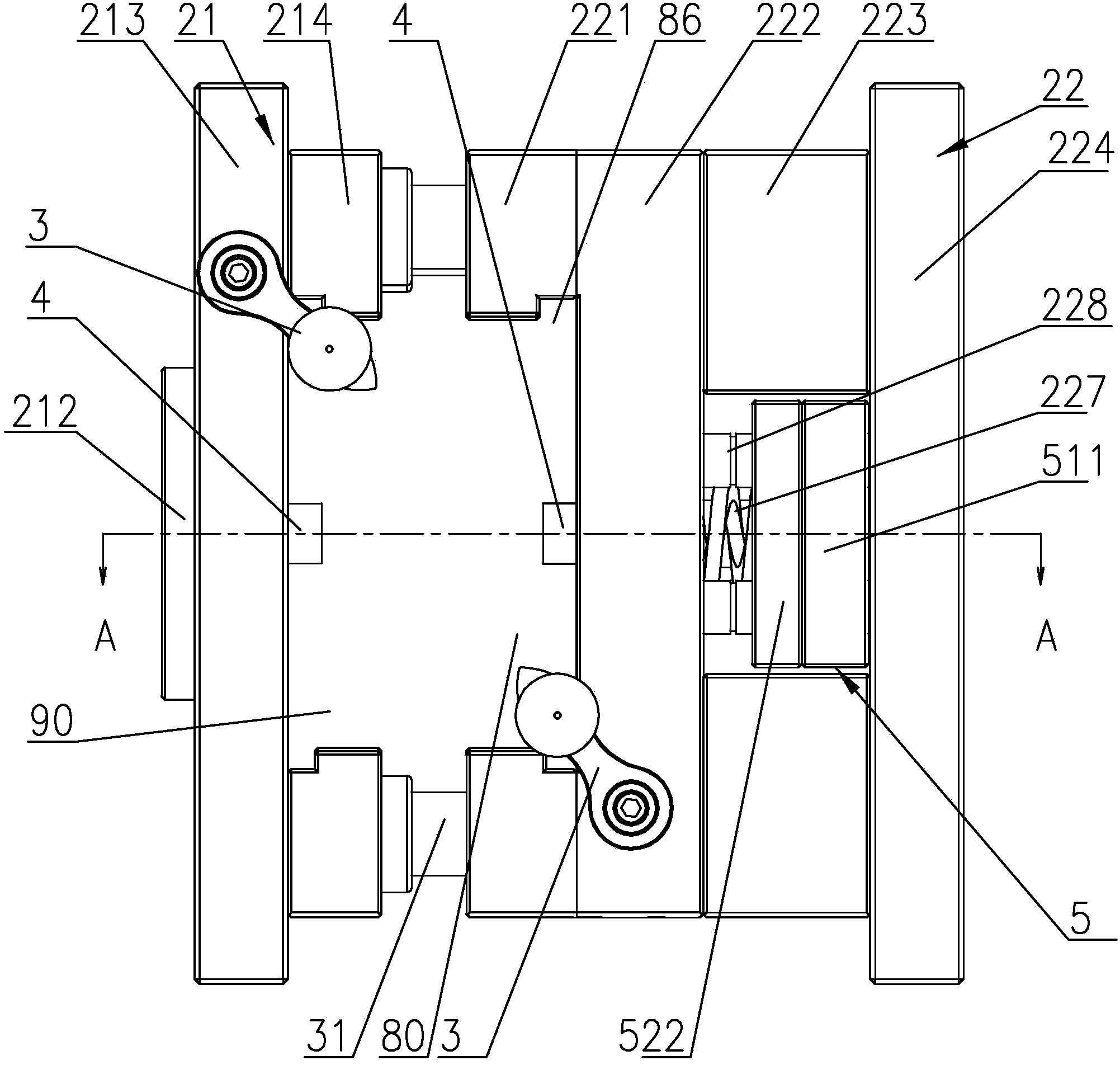
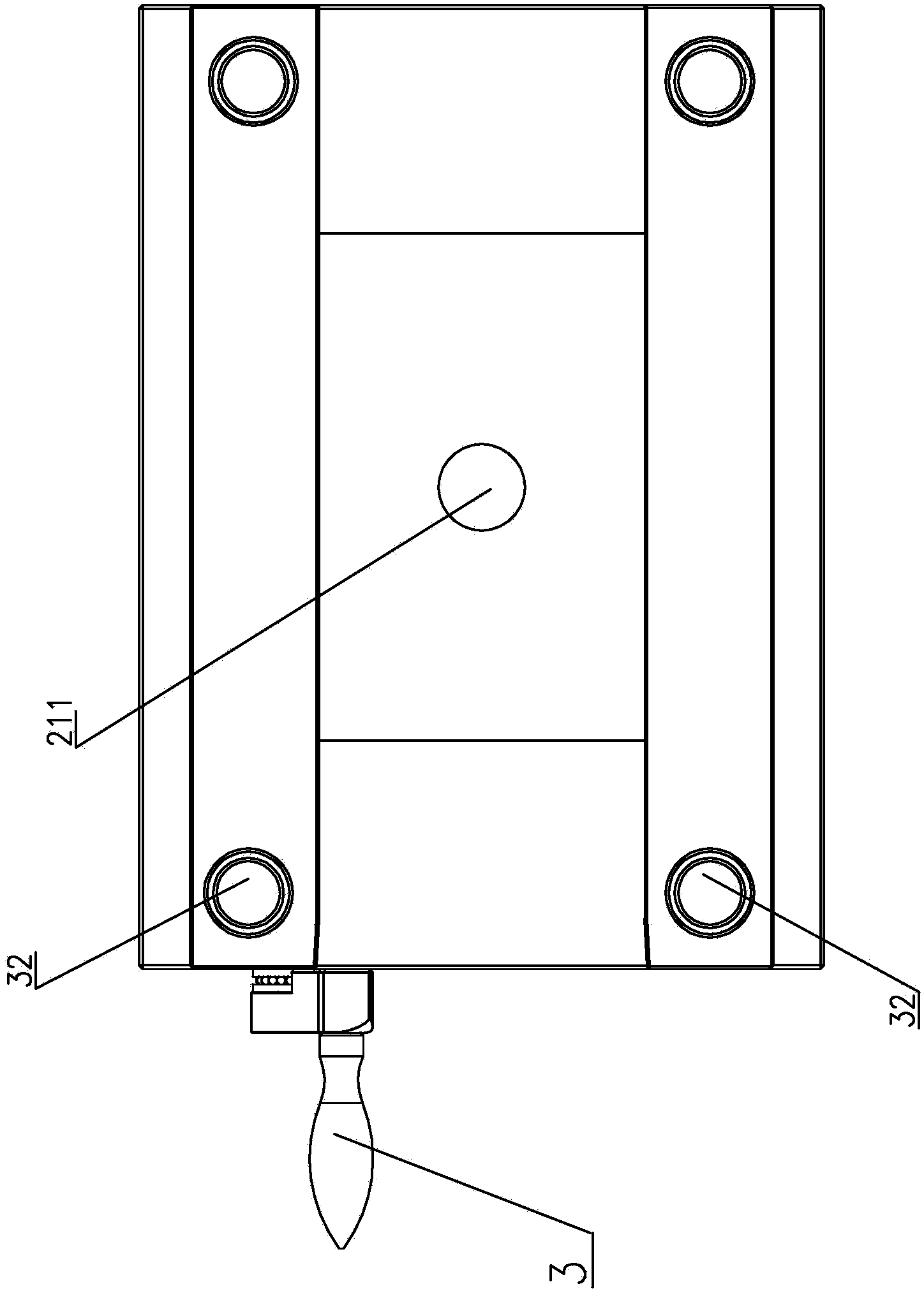
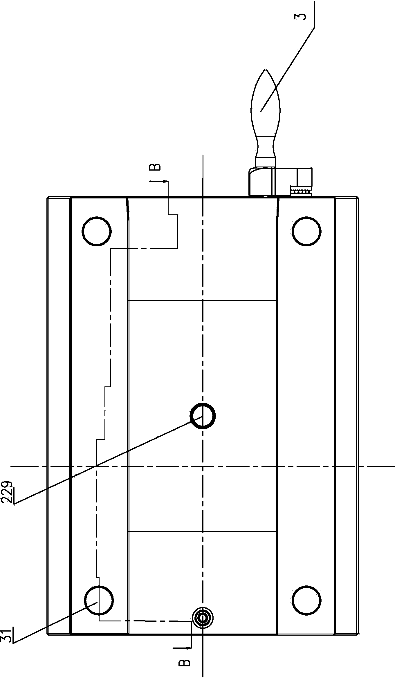
[0056] Such as Figure 1-12 , 19 shows an easy-to-release injection mold of the present invention. In this embodiment, the test standard sample is made, see Picture 9 , The injection mold is composed of a movable mold and a fixed mold. Among them, the movable mold and the fixed mold include forming parts, an ejection mechanism, a mold guide part and a pouring system. The main body of the movable mold is composed of a movable mold base 22 and a movable mold base 22. The main body of the fixed mold is composed of a fixed mold base 21 and a fixed mold core 11 movably mounted on the fixed mold base 21. The movable mold base 22 and the fixed mold base 21 are collectively called the mold base, and the movable mold core 12 The mold core 11 and the fixed mold core 11 are collectively called the mold core. The mold core is a movable molding part separated from the mold base. The mold core is a cube-shaped block. The injection mold cavity is set in the mold core. The mold cavity on the fi...

Embodiment 2

[0077] Such as Figure 13-18 As shown, the difference between this embodiment and embodiment 1 is that the injection mold cavity on the mold core is different, see Figure 15 The injection molded parts applicable to the mold core of this embodiment are the cantilever beam 91, the bending standard test strip 92, and the impact standard test strip 93. Two movable inserts 70, 71 are provided on the clamping surface of the fixed mold core 11. The movable inserts are distributed back and forth around the pouring hole (that is, the inner channel 54 of the sprue sleeve). There are two mold cavities 73 on the clamping surface of the movable mold core 12, and the two mold cavities on the movable mold core and The movable inserts 70 and 71 correspond to each other. When the mold is closed, the movable insert is located in the cavity of the movable core to form 4 injection cavities for injection molding of a single injection molded part. That is, the movable inserts 70 and 71 are respectiv...


PUM


Abstract

The invention discloses an injection mould capable of being easily de-molded. The injection mould is formed by a movable mould and a fixed mould, which are used as the injection mould, wherein each one of the movable mould and the fixed mould comprises a molding part, a pushing-out mechanism, a mould guide part and a pouring system; a mould cavity is arranged in the mould; the mould cavity is arranged on the mould closing face of the single injection mould, namely, the mould cavity is arranged on the mould closing face of the movable mould or the mould closing face of the fixed mould; the mould closing face of the other injection mould has no mould cavity and is a plane; the movable mould and the fixed mould are closed to form the complete injection mould cavity. According to the injection mould disclosed by the invention, the structure of only arranging the mould cavity on the single injection mould is applicable to injection of a standard test sample strip or an injection piece with the similar shape. The injection mould has the beneficial effects of being beneficial to simplification of the structure of the mould, improving the manufacturability of the mould and reducing the cost of the mould.

Description

Technical field [0001] The invention relates to a mold, in particular to an injection mold that is easy to demold, and is suitable for injection molding to produce plastic standard test specimens, plastic products, rubber products and the like. Background technique [0002] Synthetic materials (including modified materials such as plastics and rubber) are one of the important materials used in daily life. In recent years, with the continuous improvement of the technical level in various fields, the requirements for synthetic materials have also increased accordingly. For example, in the automotive field, some auto parts must have high temperature resistance and high strength performance, while some are used as interior decoration parts. It is required to have good surface finish, small specific gravity and considerable toughness; in the field of household appliances, the plastic shell of electrical products requires a certain appearance quality, temperature resistance within a ce...

Claims


Application Information

Patent Timeline
Patent Type & Authority Applications(China)
IPC IPC(8): B29C45/33B29C45/27B29C45/40
Inventor 陈琪
Owner 广州现代塑料有限公司
Why Eureka
Try Eureka