contact stress sensor

A contact stress and sensor technology, applied in the field of sensors, can solve the problems of small thickness of foil strain gauges, complicated processes, poor temperature characteristics of devices, etc., and achieve the effects of easy popularization and use, obvious changes in length, and obvious changes in resistance value.

Inactive Publication Date: 2015-12-16
UNIV OF ELECTRONICS SCI & TECH OF CHINA
View PDF6 Cites 2 Cited by
  • Summary
  • Abstract
  • Description
  • Claims
  • Application Information

AI Technical Summary

Problems solved by technology

[0002] The two curved surfaces of the curved slit structure are generally supported by an elastic medium. Real-time measurement of the contact stress on the upper and lower contact surfaces of the elastic medium is of special value: on the one hand, the monitoring results can be used as a reference for external standard operations, and on the other hand, it can be used as a reference for extreme environments. However, due to space constraints, the measurement of contact stress is still a difficult point in measurement technology. The common foil strain gauge has a small thickness and an approximate planar structure, which can be placed in a small enough slit Among them, but the structural design and principle of this kind of strain gauge determine that it can only be used to test the tensile force, and cannot be directly used for the test of the contact stress. Although the general contact stress sensor can be installed in the slit, because of Based on the piezoresistive effect, the problems of poor temperature characteristics of the device and complex process have not been well resolved

Method used


Image

  • contact stress sensor
  • contact stress sensor
  • contact stress sensor

Examples


Embodiment 1

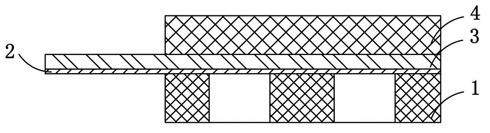
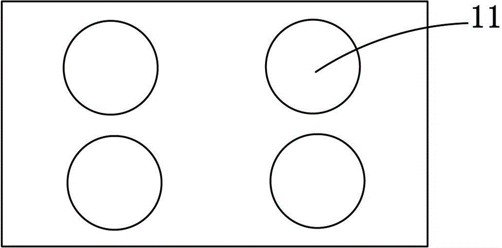
[0025] Such as figure 1 , figure 2 As shown, the contact stress sensor in this embodiment includes a flexible support base 1 with four circular through holes 11, a strain gauge 2, a flexible transmission line 3 and a flexible medium 4, wherein the flexible support base 1 is located at the bottom, and the strain The meter 2 and the flexible transmission line 3 are connected as a whole by wire bonding and then bonded to the upper surface of the flexible support base 1 by AB glue. Four circular through-holes 11 are also the main structure that enables the contact stress sensor in this embodiment to be used for contact stress monitoring. Due to the existence of these holes, under the action of force, the strain gauge 2 on the flexible support base 1 Simultaneous bending and deformation of multiple parts corresponding to the position of the through hole 11 makes the length change of the sensitive grid in the strain gauge 2 more obvious in a smaller thickness range, that is, the c...

Embodiment 2

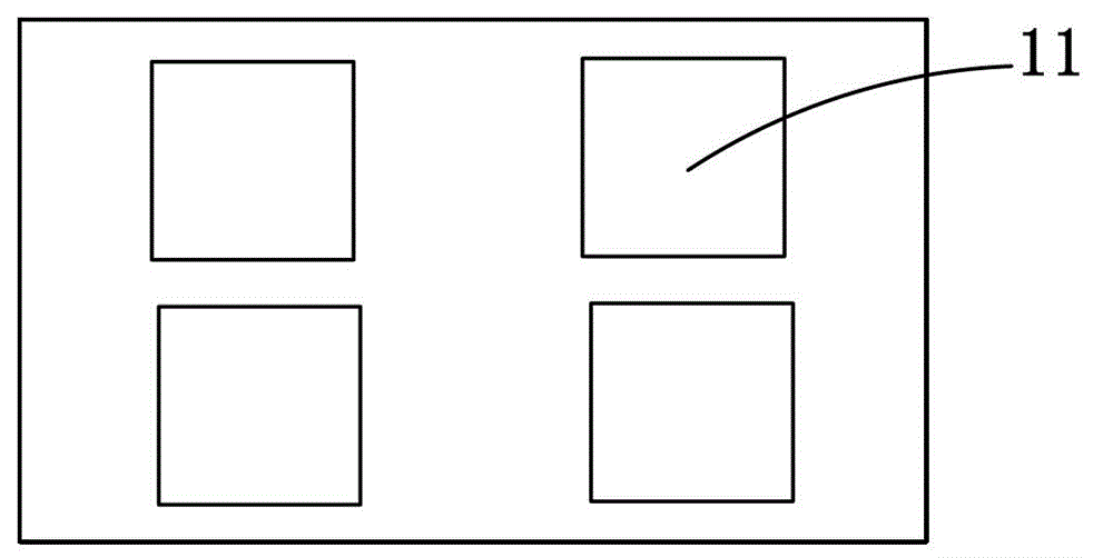
[0030] The structure and working principle of the contact stress sensor in this embodiment are the same as that of the contact stress sensor in Embodiment 1, the difference is that four square through holes 11 are arranged on the flexible support base plate in this embodiment; The material of the flexible support substrate 1 of the contact stress sensor is polyimide with an elastic modulus of 2.25 GPa, and the material of the flexible medium 4 is rubber with an elastic modulus of 25 MPa.

Embodiment 3

[0032] The structure and working principle of the contact stress sensor in this embodiment are the same as that of the contact stress sensor in Embodiment 1, the difference is that four rectangular through holes 11 are arranged on the flexible support base plate in this embodiment; The material of the flexible support substrate 1 of the contact stress sensor is polyimide with an elastic modulus of 4GPa, and the material of the flexible medium 4 is rubber with an elastic modulus of 50MPa.

[0033] The number of through holes on the flexible support base in the above embodiments is not limited to four.


PUM

PropertyMeasurementUnit
elastic modulusaaaaaaaaaa

Abstract

The invention discloses a contact stress sensor, which comprises a flexible support substrate provided with several through holes, a strain gauge, a flexible transmission line and a flexible medium, wherein the flexible support base is located at the bottom, and the strain gauge and the flexible transmission line are connected by wire bonding. A whole is bonded to the upper surface of the flexible support base, and the flexible medium is covered and bonded to the upper surface of the strain gauge and the flexible transmission line. By using a flexible support base, flexible transmission line and flexible medium, the contact stress sensor can be bent and deformed with the change of the installation environment, and is especially suitable for the measurement of the contact stress of the upper and lower contact surfaces of objects in a curved surface structure; through the support base A number of through holes are arranged on the upper surface, which not only enables the strain gauge which can only be used to test the tensile stress, but also can be used for the test of the compressive stress, and improves the accuracy of the test.

Description

technical field [0001] The invention belongs to the technical field of sensors, and in particular relates to a contact stress sensor. Background technique [0002] The two curved surfaces of the curved slit structure are generally supported by an elastic medium. Real-time measurement of the contact stress on the upper and lower contact surfaces of the elastic medium is of special value: on the one hand, the monitoring results can be used as a reference for external standard operations, and on the other hand, it can be used as a reference for extreme environments. However, due to space constraints, the measurement of contact stress is still a difficult point in measurement technology. The common foil strain gauge has a small thickness and an approximate planar structure, which can be placed in a small enough slit Among them, but the structural design and principle of this kind of strain gauge determine that it can only be used to test the tensile force, and cannot be directly...

Claims


Application Information

Patent Timeline
Patent Type & Authority Patents(China)
IPC IPC(8): G01L1/22
Inventor 丁杰雄边志远褚博文赵旭东刘广民何建国邓梦付振华李海宁姜忠关利超
Owner UNIV OF ELECTRONICS SCI & TECH OF CHINA
Why Eureka
Try Eureka