a sound barrier

A technology of sound barriers and sound-absorbing panels, applied in the field of sound barriers of high-speed railways and high-speed railway noise control, can solve the problem of installation and fixing structures without further consideration of on-site construction needs, no exploration of new material technologies, and difficult processing of sound-absorbing panels, etc. Problems, to achieve the effect of convenient material transportation, excellent noise reduction function, stable size

Active Publication Date: 2015-11-18
CHENGDU ZHONGHONG RAIL TRANSIT ENVIRONMENTAL PROTECTION IND +1
View PDF6 Cites 0 Cited by
  • Summary
  • Abstract
  • Description
  • Claims
  • Application Information

AI Technical Summary

Problems solved by technology

Acoustic panels made of these materials are not easy to process and can irritate the skin
Therefore, its application is also limited
In addition, organic foam materials have also been used for sound barriers, but they have been gradually withdrawn due to poor fire resistance and low strength.
[0004] The sound barrier research has not only made great progress in the selection of material properties, but also in-depth research on the sound barrier structure. The existing sound barrier structures mostly use a single metal material or inorganic non-metallic material structure, and the layout is not based on the high-speed railway. The design is based on the characteristics, and the installation and fixed structure did not further consider the needs of on-site construction, nor did it combine the continuous development of new materials for comprehensive technical exploration to meet the higher requirements of noise control.

Method used


Image

  • a sound barrier
  • a sound barrier
  • a sound barrier

Examples


Embodiment Construction

[0026] The present invention is specifically described below by way of embodiment, and present embodiment is only used to further illustrate the present invention, but can not be interpreted as the restriction to protection scope of the present invention, some non-compliances that those skilled in the art make according to the content of the present invention above-mentioned Essential improvements and adjustments also belong to the protection scope of the present invention.

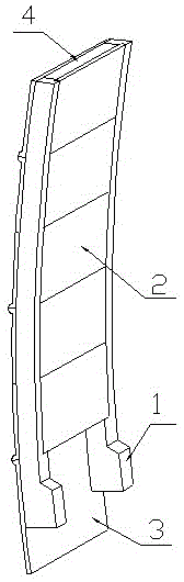
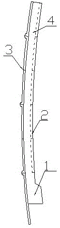
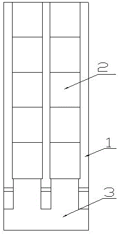
[0027] combine Figure 1 to Figure 5 .

[0028] As shown in the figure, the sound barrier includes supporting rib columns 1 arranged continuously and at intervals along the railway track line. The supporting rib columns 1 are fixedly installed on the structure of the railway foundation 6, and the side of the railway traffic surface between every two supporting rib columns 1 is installed and fixed. There is a sound-absorbing board 2, and a backboard 3 is installed and fixed on the back side, and a hollow ...


PUM


Abstract

The invention discloses a sound barrier. Including supporting ribs, sound-absorbing panels and the back, a hollow structure is formed between the sound-absorbing panels and the back panel, and the supporting ribs are consolidated on the railway foundation; the sound-absorbing panels are micropores with a disorderly connected three-dimensional mesh structure The ceramic composite board; the sound barrier formed by the supporting rib column, the sound-absorbing panel and the back plate is an arc surface, and the concave surface of the arc surface faces the railway traffic surface; the lower edge of the back plate protrudes from the bottom of the supporting rib column. The invention adopts a three-layer hollow sound-absorbing sound barrier structure, and the sound-absorbing board adopts a microporous ceramic composite board, which not only has excellent noise reduction function, but also has better processing performance; the noise reduction barrier adopts an arc surface structure It has better sound absorption and reflection performance, and can further reduce noise spillage. Tests have proved that the sound barrier of the present invention has better sound absorption performance, high sound absorption coefficient, wide sound absorption frequency band, and good low-frequency sound absorption effect; the prefabricated structure of the sound barrier of the present invention is more convenient to process and install, and has higher construction efficiency.

Description

technical field [0001] The invention belongs to the technical field of railway operation noise control, in particular to the high-speed railway noise control technology, in particular to a sound barrier applied to high-speed railways. Background technique [0002] The sound barrier is a facility inserted between the sound source and the receiver, so that the sound wave propagation has a significant additional attenuation, thereby reducing the impact of noise in a certain area where the receiver is located. [0003] The sound-absorbing material used in the high-speed rail sound barrier, first of all, its sound-absorbing performance should meet the structural design requirements of the sound barrier, and its noise reduction coefficient NRC>0.5; as a sound-absorbing material for outdoor use, it should also have good mechanical properties and weather resistance , not only can withstand the combined effect of train aerodynamic force and wind load, but also can withstand wind a...

Claims


Application Information

Patent Timeline
Patent Type & Authority Patents(China)
IPC IPC(8): E01F8/00
Inventor 陈松王其昌
Owner CHENGDU ZHONGHONG RAIL TRANSIT ENVIRONMENTAL PROTECTION IND
Why Eureka
Try Eureka