Supercharge Your Innovation With Domain-Expert AI Agents!

Scanning module and scanning exposure compensating method

A technology of scanning module and compensation method, which is applied to the parts and electrical components of TVs and color TVs, etc., can solve the problems such as affecting the scanning results, slowing the relative movement speed between the light sensor and the object, and different photosensitive time. , to achieve the effect of reducing exposure requirements

Active Publication Date: 2014-01-22
全友电脑科技(吴江)有限公司
View PDF4 Cites 0 Cited by
  • Summary
  • Abstract
  • Description
  • Claims
  • Application Information

AI Technical Summary

Problems solved by technology

However, during the scanning process, it may be difficult to maintain a certain relative moving speed between the light sensor and the object, so that the light sensor may have different photosensitive times for the image beams from different image areas.
In this way, it will affect the scanning result of the scanner on the object
[0003] For example, during the scanning process, if the computing speed of the computer connected to the scanner suddenly slows down, it may cause the relative movement speed between the light sensor and the object to suddenly slow down

Method used


Image

  • Scanning module and scanning exposure compensating method
  • Scanning module and scanning exposure compensating method
  • Scanning module and scanning exposure compensating method

Examples


Embodiment Construction

[0050] In order to make the object, technical solution and advantages of the present invention clearer, the embodiments of the present invention will be further described in detail below in conjunction with the accompanying drawings. Here, the exemplary embodiments and descriptions of the present invention are used to explain the present invention, but not to limit the present invention.

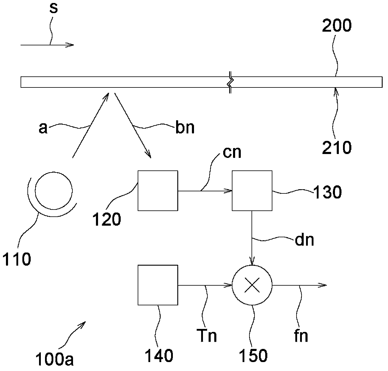
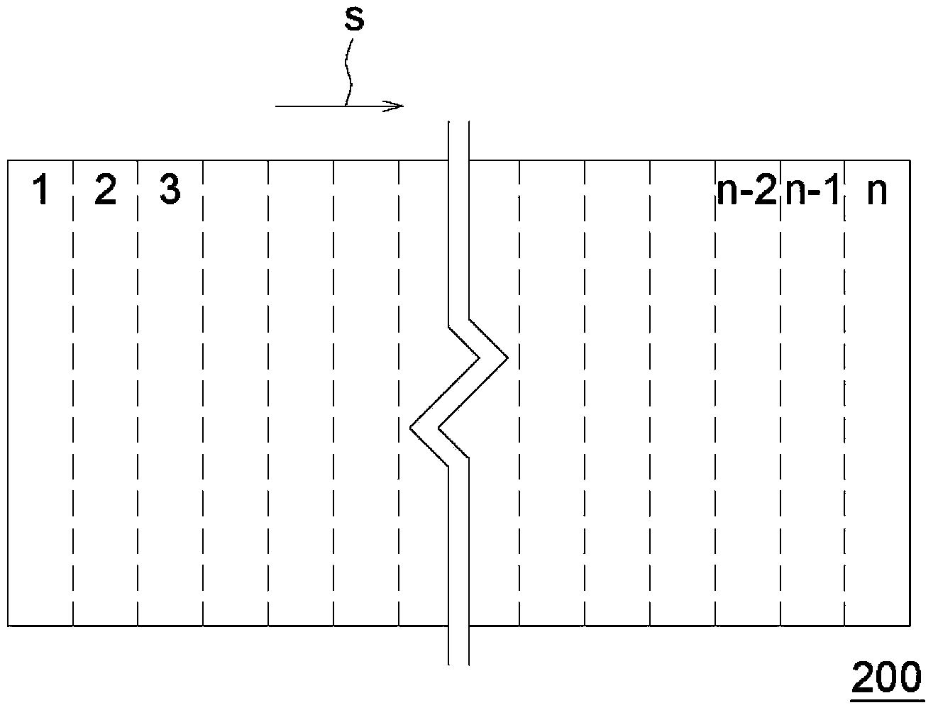
[0051] figure 1 A schematic structural diagram of a scanning module according to an embodiment of the present invention is drawn, and figure 2 draw out figure 1 Bottom view of objects in . For illustrative purposes, figure 2 Multiple image areas are separated by dotted lines in , and the size of each image area of ​​the object is enlarged. In addition, in the following embodiments, the object is a flat file as an example for illustration, but in other unillustrated embodiments, the object may also be a three-dimensional object. In addition, the following embodiments take the scanning ...


PUM


Abstract

The embodiment of the invention discloses a scanning module and a scanning exposure compensating method. The scanning module comprises a light sensor, an analog front end element, a timer and a digital compensation and equalization element. The light sensor is arranged on a transmission path of a plurality of imaging beams formed by the condition that a plurality of imaging regions of an object are exposed to an illumination beam, and is suitable to sense the imaging beams in sequence for outputting a plurality of analog signals in sequence. The analog front end element is electrically connected with the light sensor and is suitable to convert the analog signals into a plurality of digital signals in sequence. The timer is suitable to calculate a sensing time of the light sensor sensing each imaging beam. The digital compensation and equalization element is electrically connected with the analog front end element and the timer, and is suitable to compensate the corresponding digital signal according to each sensing time.

Description

technical field [0001] The present invention relates to a scanning module and a scanning exposure compensating method (scanning exposure compensating method), and in particular to a method for compensating according to the sensing time of each image beam by a light sensor. A digital signal scanning module and a scanning exposure compensation method. Background technique [0002] Generally speaking, a scanner uses a light source to expose multiple imaging regions of an object to form multiple imaging beams. Then, use the light sensor to sequentially sense these image beams, convert the sensing results into digital signals, and then output them into electronic files, so that users can store them in storage devices such as hard disks or passed through the network. However, during the scanning process, it may be difficult to maintain a certain relative moving speed between the light sensor and the object, so that the light sensor may have different photosensitive times for ima...

Claims


Application Information

Patent Timeline
Patent Type & Authority Applications(China)
IPC IPC(8): H04N1/024H04N5/351
Inventor 余国晖
Owner 全友电脑科技(吴江)有限公司
Features
  • R&D
  • Intellectual Property
  • Life Sciences
  • Materials
  • Tech Scout
  • Unparalleled Data Quality
  • Higher Quality Content
  • 60% Fewer Hallucinations
Learn More