Novel locking mechanism

A locking mechanism, a new type of technology, used in building locks, building construction, locks in accident situations, etc.

Active Publication Date: 2014-02-12
YANFENG ADIENT SEATING CO LTD
View PDF5 Cites 22 Cited by
  • Summary
  • Abstract
  • Description
  • Claims
  • Application Information

AI Technical Summary

Problems solved by technology

[0004] The technical problem to be solved by the present invention is to provide a new type of locking mechanism for the problems existing in the existing push-push restraint mechanism

Method used


Image

  • Novel locking mechanism
  • Novel locking mechanism
  • Novel locking mechanism

Examples


Embodiment 1

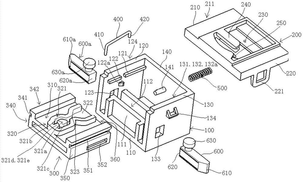
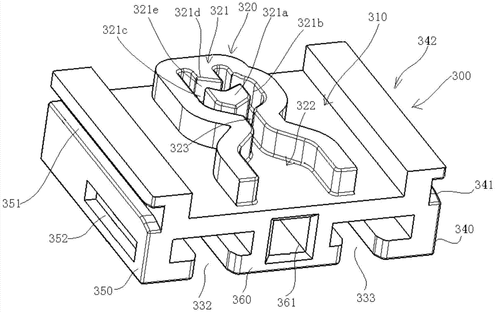
[0090] see Figure 1 to Figure 6 , The new locking mechanism of this embodiment shown in the figure includes a lower housing 100, an upper housing 200, a slider 300, a labyrinth swing locking lever 400, a slider ejection spring 500 and a pair of locking pins 600, 600a.

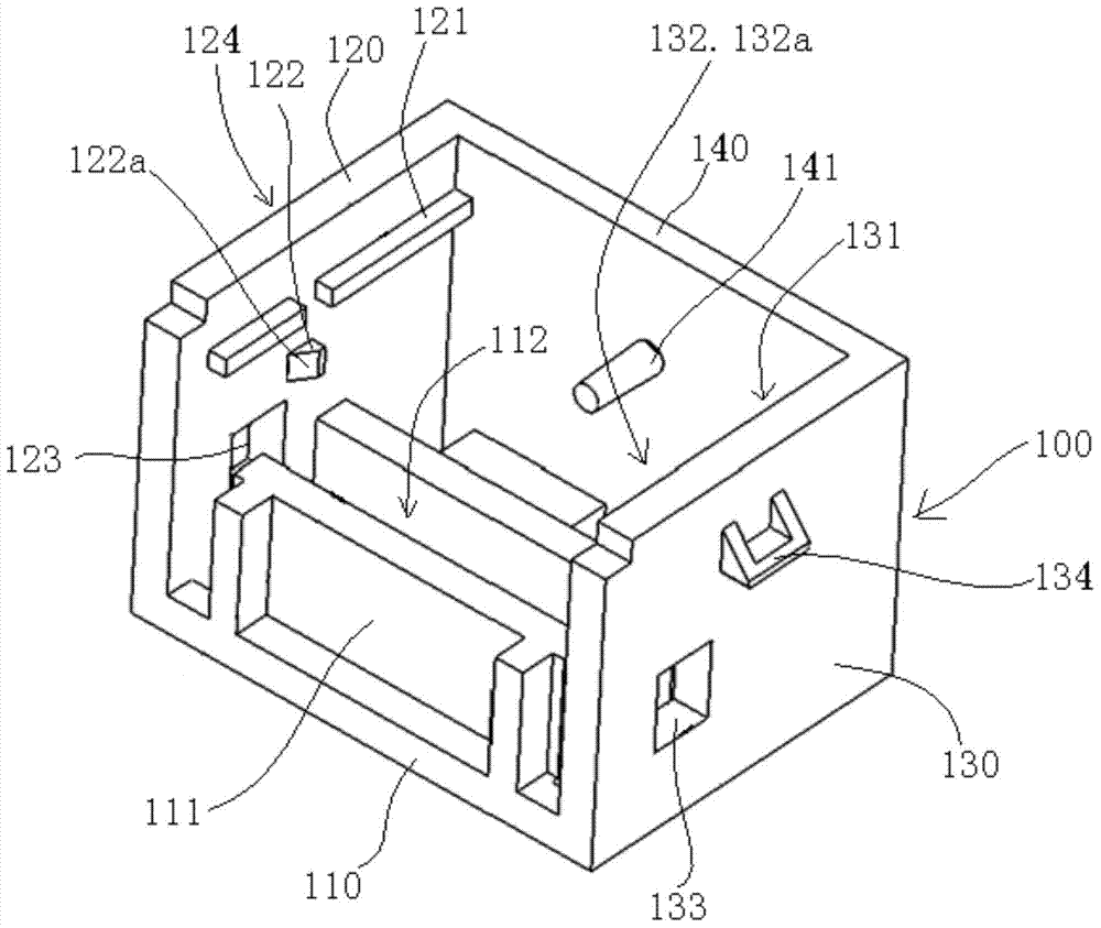
[0091] The entire lower case 100 is composed of a bottom plate 110, a left side plate 120, a right side plate 130, and a rear side plate 140, and its top and front sides are open. A slide rail 121,131 and a limit block 122,132 are respectively arranged on the top of the inner surface of the left and right side plates 120,130, and the limit block 122,132 is respectively positioned at the below of the slide rail 121,131, and the limit block The sides 122, 132 facing the front side of the lower housing 100 are inclined surfaces 122a, 132a.

[0092]A spring mounting post 141 is disposed at a middle position on the inner surface of the rear side plate 140 . A U-shaped block 111 is installed on the bottom plate 11...

Embodiment 2

[0117] The difference between the novel locking mechanism of this embodiment and the novel locking mechanism of Embodiment 1 is that an inertia lock block 700 and an inertia lock block compression spring 800 are added, and the specific structure is as follows:

[0118] see Figure 26 to Figure 31 , the new locking mechanism of this embodiment includes a lower housing 100, an upper housing 200, a slider 300, a labyrinth swing locking lever 400, a slider ejection spring 500, a pair of locking pins 600, 600a, and an inertial locking block 700 And an inertia lock block stage clip 800.

[0119] The entire lower case 100 is composed of a bottom plate 110, a left side plate 120, a right side plate 130, and a rear side plate 140, and its top and front sides are open. A slide rail 121,131 and a limit block 122,132 are respectively arranged on the top of the inner surface of the left and right side plates 120,130, and the limit block 122,132 is respectively positioned at the below of t...


PUM


Abstract

The invention discloses a novel locking mechanism, which comprises an upper shell, a lower shell and a slider, wherein the slider is arranged in the lower shell in a sliding manner, is driven by a slider ejecting spring to extend out of the lower shell or be contracted in the lower shell and is used for carrying a cup rack, an ashtray or a storage box, one end of a maze swing locking rod is hooked on the upper shell, the other end of the maze swing locking rod is hooked on a locking block in a maze locking mechanism on the slider, the hook end at the other end of the maze swing locking rod is capable of being separated from the locking block for unlocking the slider after the slider is subjected to inwards pushing force, the novel locking mechanism also comprises a locking pin which is arranged in the lower shell and is driven by the slider to move, and a locking matching relation is formed between the outer end of the locking pin and the lower shell. The problem that the bearing pulling force of a common push-push type mechanism is over small is solved, and the problem that when accidents, such as sudden braking, are encountered, the common push-push type mechanism can obtain accelerated speed consistent with the unlocking direction, the slider moves along the unlocking direction, so that the mechanism is unlocked by self is also solved.

Description

technical field [0001] The present invention relates to a locking mechanism for locking two components, in particular to a novel locking mechanism for closing and opening a switch cover on accessories such as cup holders, ashtrays and storage boxes. Background technique [0002] At present, it is more convenient to use the push-push restraint mechanism on the accessories in the compartments such as cup holders, ashtrays and storage boxes for closing and opening the switch cover, but the common push-push restraint mechanism is When the lock block in the labyrinth locking mechanism on the slider is hooked by a hook end of the labyrinth swing lock rod, the maximum pulling force that the slider can carry cannot be greater than the shear force of a hook end of the labyrinth swing lock rod, so it cannot withstand too much Big pull. [0003] In addition, when the lock block in the labyrinth lock mechanism on the slider is hooked by a hook end of the labyrinth swing lock lever, whe...

Claims


Application Information

Patent Timeline
Patent Type & Authority Applications(China)
IPC IPC(8): E05B63/00E05B77/04
Inventor 欧阳砚武宋卿李侠徐东海
Owner YANFENG ADIENT SEATING CO LTD
Why Eureka
Try Eureka