Unlock instant, AI-driven research and patent intelligence for your innovation.
a locking mechanism
What is Al technical title?
Al technical title is built by PatSnap Al team. It summarizes the technical point description of the patent document.
A locking mechanism, technology of the locking part, applied in the direction of building locks, building construction, locks in accident situations, etc.
Active Publication Date: 2016-08-10
YANFENG ADIENT SEATING CO LTD
View PDF5 Cites 0 Cited by
Summary
Abstract
Description
Claims
Application Information
AI Technical Summary
This helps you quickly interpret patents by identifying the three key elements:
Problems solved by technology
Method used
Benefits of technology
Problems solved by technology
[0004] The technical problem to be solved by the present invention is to provide a locking mechanism for the problems existing in the existing push-push restraint mechanism
Method used
Image
Click on the blue label to locate the original text in one second.
Reading with bidirectional positioning of images and text.
Examples
Embodiment 1
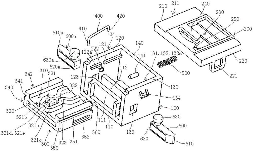
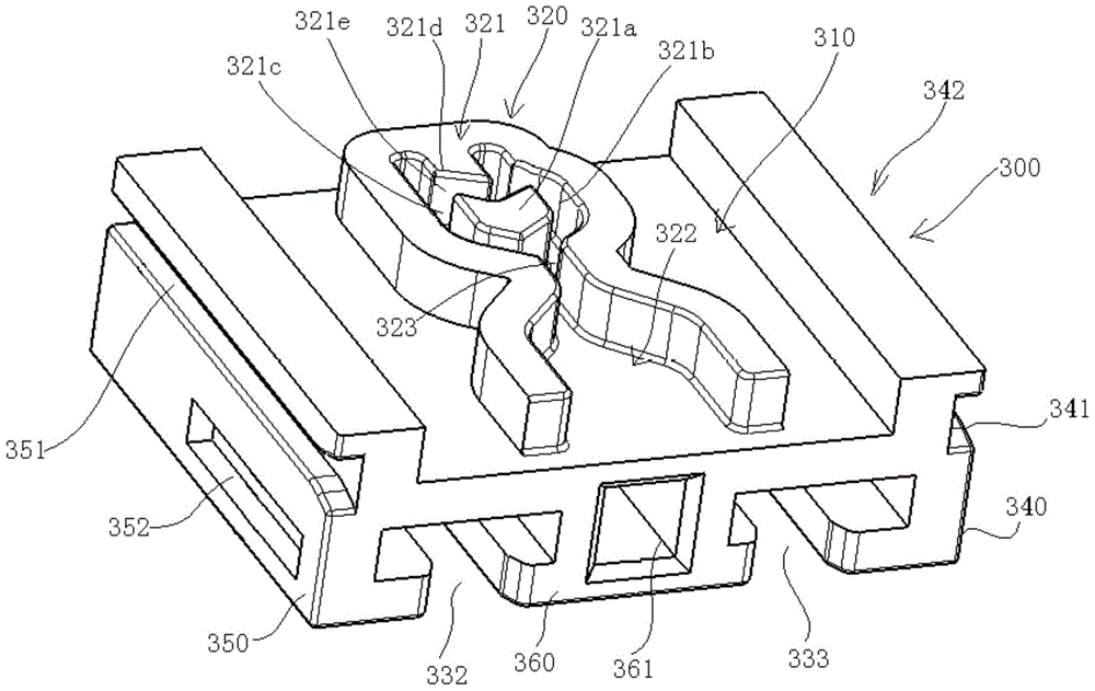
[0090] see Figure 1 to Figure 6 , The locking mechanism of this embodiment shown in the figure includes a lower housing 100, an upper housing 200, a slider 300, a labyrinth swing locking lever 400, a slider ejection spring 500 and a pair of locking pins 600, 600a.
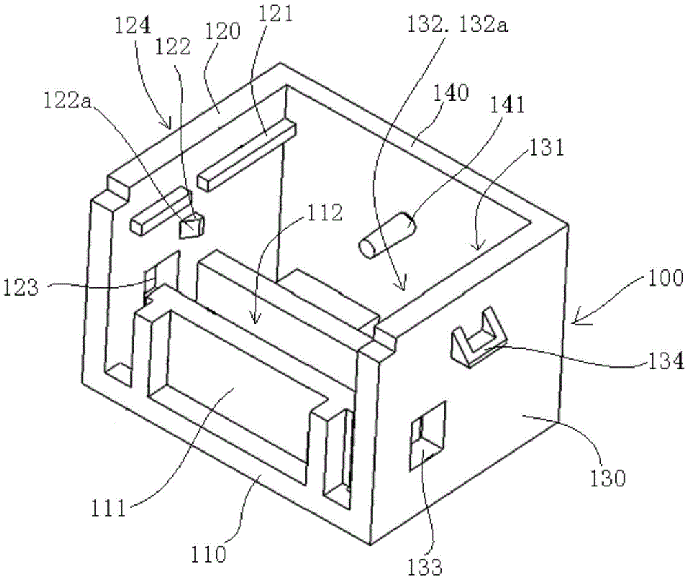
[0091] The entire lower case 100 is composed of a bottom plate 110, a left side plate 120, a right side plate 130, and a rear side plate 140, and its top and front sides are open. A slide rail 121,131 and a limit block 122,132 are respectively arranged on the top of the inner surface of the left and right side plates 120,130, and the limit block 122,132 is respectively positioned at the below of the slide rail 121,131, and the limit block The sides 122, 132 facing the front side of the lower housing 100 are inclined surfaces 122a, 132a.
[0092] A spring mounting post 141 is disposed at a middle position on the inner surface of the rear side plate 140 . A U-shaped block 111 is installed on the bottom plate 110, ...
Embodiment 2
[0117] The difference between the locking mechanism of this embodiment and the locking mechanism of Embodiment 1 is that an inertia lock block 700 and an inertia lock block compression spring 800 are added, and the specific structure is as follows:
[0118] see Figure 26 to Figure 31 , the locking mechanism of this embodiment includes a lower housing 100, an upper housing 200, a slider 300, a labyrinth swing locking lever 400, a slider ejection spring 500, a pair of locking pins 600, 600a, an inertial locking block 700 and An inertia lock block stage stage 800.
[0119] The entire lower case 100 is composed of a bottom plate 110, a left side plate 120, a right side plate 130, and a rear side plate 140, and its top and front sides are open. A slide rail 121,131 and a limit block 122,132 are respectively arranged on the top of the inner surface of the left and right side plates 120,130, and the limit block 122,132 is respectively positioned at the below of the slide rail 121,1...
PUM
Abstract
A locking mechanism disclosed in the present invention comprises: upper and lower casings and a slider slidingly arranged in the lower casing, the slider is driven by the slider ejection spring to extend or retract from the lower casing and is used to carry the cup holder , ashtray or storage box; one end of the labyrinth swing lock lever is hooked on the upper casing, and the other end is hooked on the lock block in the labyrinth locking mechanism on the slider, and after the slider is pushed inward, the labyrinth The hook end at the other end of the swing lock rod can be disengaged from the lock block to unlock the slide block; it also includes: a lock pin arranged in the lower casing and capable of being driven by the slide block, and the outer end of the lock pin is connected to the lower casing. Form a locking fit relationship between them. The present invention not only solves the problem that the pull force carried by the ordinary push-push restraint mechanism is too small, but also solves the problem that the ordinary push-push restraint mechanism may obtain an acceleration consistent with the unlocking direction when encountering an accident, such as sudden braking. , the slider will move towards the unlocking direction, causing the mechanism to unlock itself.
Description
technical field [0001] The present invention relates to a locking mechanism for locking two components, in particular to a locking mechanism for closing and opening a switch cover on accessories such as cup holders, ashtrays and storage boxes in a compartment. Background technique [0002] At present, it is more convenient to use the push-push restraint mechanism on the accessories in the compartments such as cup holders, ashtrays and storage boxes for closing and opening the switch cover, but the common push-push restraint mechanism is When the lock block in the labyrinth locking mechanism on the slider is hooked by a hook end of the labyrinth swing lock rod, the maximum pulling force that the slider can carry cannot be greater than the shear force of a hook end of the labyrinth swing lock rod, so it cannot withstand too much Big pull. [0003] In addition, when the lock block in the labyrinth lock mechanism on the slider is hooked by a hook end of the labyrinth swing lock...
Claims
Application Information
Patent Timeline
Application Date:The date an application was filed.
Publication Date:The date a patent or application was officially published.
First Publication Date:The earliest publication date of a patent with the same application number.
Issue Date:Publication date of the patent grant document.
PCT Entry Date:The Entry date of PCT National Phase.
Estimated Expiry Date:The statutory expiry date of a patent right according to the Patent Law, and it is the longest term of protection that the patent right can achieve without the termination of the patent right due to other reasons(Term extension factor has been taken into account ).
Invalid Date:Actual expiry date is based on effective date or publication date of legal transaction data of invalid patent.

