Roller device

A technology of equipment and guide rollers, applied in the direction of roller table, roller column, semiconductor/solid-state device manufacturing, etc., can solve problems such as damage to transfer objects and reduction of product production efficiency

A technology of equipment and guide rollers, applied in the direction of roller table, roller column, semiconductor/solid-state device manufacturing, etc., can solve problems such as damage to transfer objects and reduction of product production efficiency

CN103625876AInactive Publication Date: 2014-03-12SNU PRECISION CO LTD

Image

  • Roller device
  • Roller device
  • Roller device

Examples


Embodiment Construction

[0019] Hereinafter, an embodiment of a guide roller apparatus according to the present invention will be described with reference to the accompanying drawings.

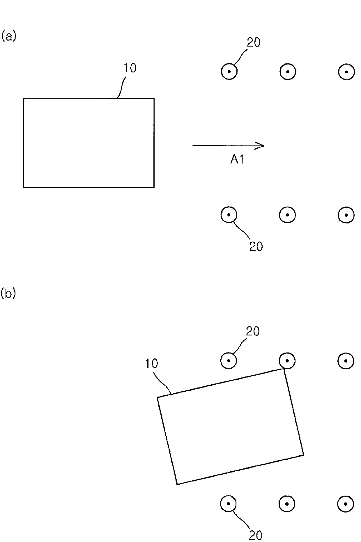
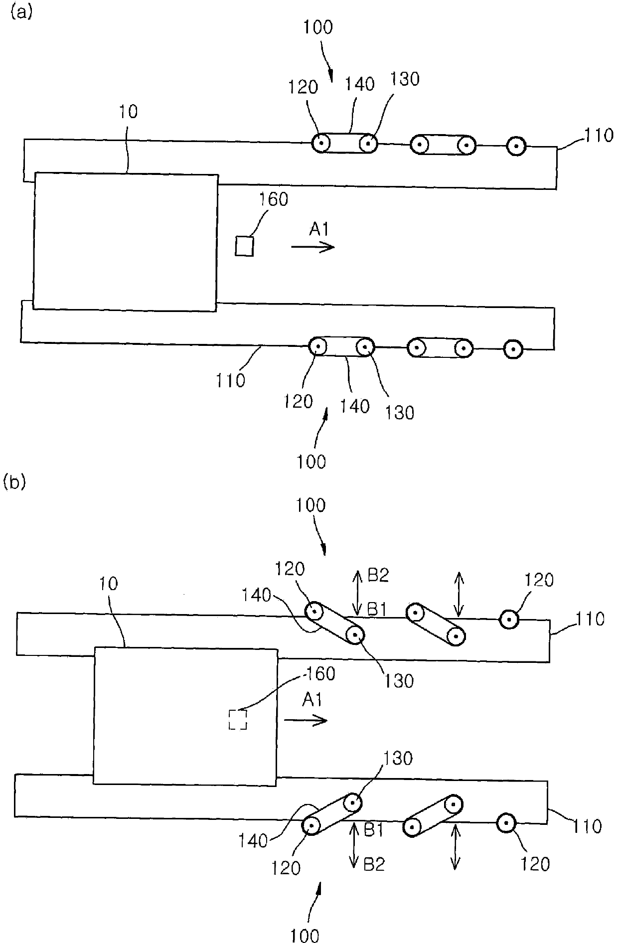
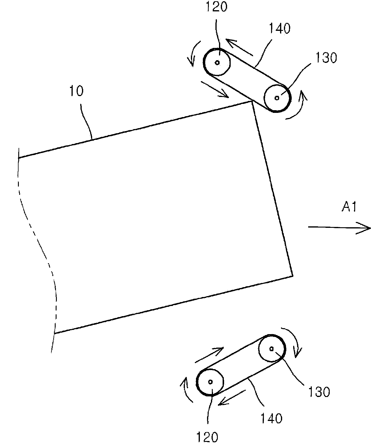
[0020] figure 2 is a view showing a guide roller device according to an embodiment of the present invention; image 3 to show the figure 2 The view of the first roller, the second roller and the belt rotated by the first roller rotary drive of the guide roller device; Figure 4 To illustrate when the passed object is not passed along the passed direction figure 2 a view of the operation of the second roll of the guide roll apparatus; and Figure 5 for showing figure 2 View of the spring member of the guide roller device.

[0021] refer to Figure 2 to Figure 5 , the guide roller device 100 in this embodiment includes a transfer unit 110, a plurality of first rollers 120, a second roller 130, a belt 140, a second roller moving unit (not shown), a first roller rotation driver (not shown Out), a controller (no...


PUM


Abstract

The invention disclsoes a guide roller device, which comprises a transfer part, multiple first rollers, multiple second rollers, a belt, a second roller moving part, a first roller rotating part, a torque sensor, and a control part. The transfer part transfers objects along a transfer direction. The first rollers are separately arranged in the side parts of the objects along the transfer direction to transfer the objects in the transfer direction. The second rollers are arranged between the first rollers neighboring along the side parts of the objects. The belt is wound on the first and second rollers. The second roller moving part reciprocates the second rollers in a direction to be closed to or to be escaped from the objects.

Description

technical field [0001] The present invention relates to a guide roller apparatus, and more particularly, to a guide roller apparatus that guides a transfer object at opposite sides so that the transfer object can be normally transferred in a transfer direction. Background technique [0002] When manufacturing a display substrate such as a flat display panel, various processes such as deposition, cleaning, drying, etching, exposure, etc. are performed to form patterns on the substrate. In addition, most of such processes are performed in a process chamber for performing a corresponding process, and thus, the substrate must be transferred to enter the corresponding process chamber or to be transferred from the corresponding process chamber when the process in the corresponding process chamber is completed. Remove the substrate from the process chamber. [0003] As substrate transfer methods currently used in substrate transfer equipment, there are a horizontal transfer method...

Claims


Application Information

Patent Timeline
12 Mar 2014
Publication
CN103625876A
IPC
B65G39/18
CPC
B65G13/06; B65G49/061; B65G49/067; G02F1/1303; H01L21/67706
Inventors
宋旭; 朴明进