elastic flat comb

A technology of elasticity and combing needles, which is applied in the field of hair combs, can solve problems such as the lack of elasticity of the combing needles of hair combs, and achieve the effects of saving raw materials, simplifying production and assembly steps, and reducing manufacturing costs

Inactive Publication Date: 2017-06-23
姚大球
View PDF5 Cites 0 Cited by
  • Summary
  • Abstract
  • Description
  • Claims
  • Application Information

AI Technical Summary

Problems solved by technology

The material of the hair comb is soaked in medicine to give the hair comb a certain health care effect, and although it is made of elastic and firm wood, the comb needles of the hair comb are not elastic, and the elasticity of the hair comb is no better than that of a plastic flat comb. it is good

Method used


Image

  • elastic flat comb
  • elastic flat comb
  • elastic flat comb

Examples


Embodiment 1

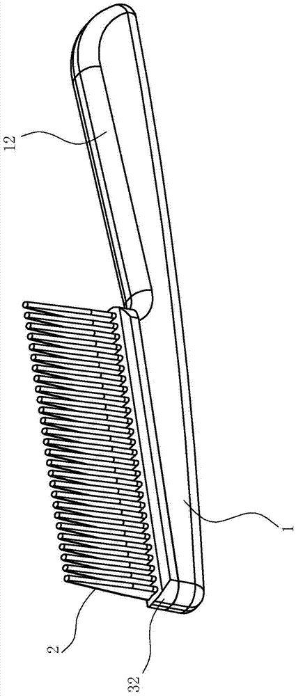
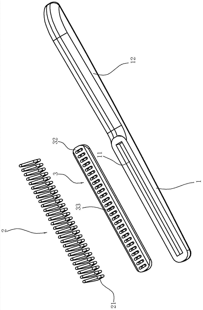
[0021] Such as Figure 1 to Figure 4 As shown, the elastic flat comb includes:

[0022] The base plate 1 is made of wood material or other materials, and the tail end of the base plate is extended to form a handle 12 for the operator to hold. A groove 11 is provided on the surface of the base plate 1 connected with the connecting base 3 . In this embodiment, the groove 11 is rectangular.

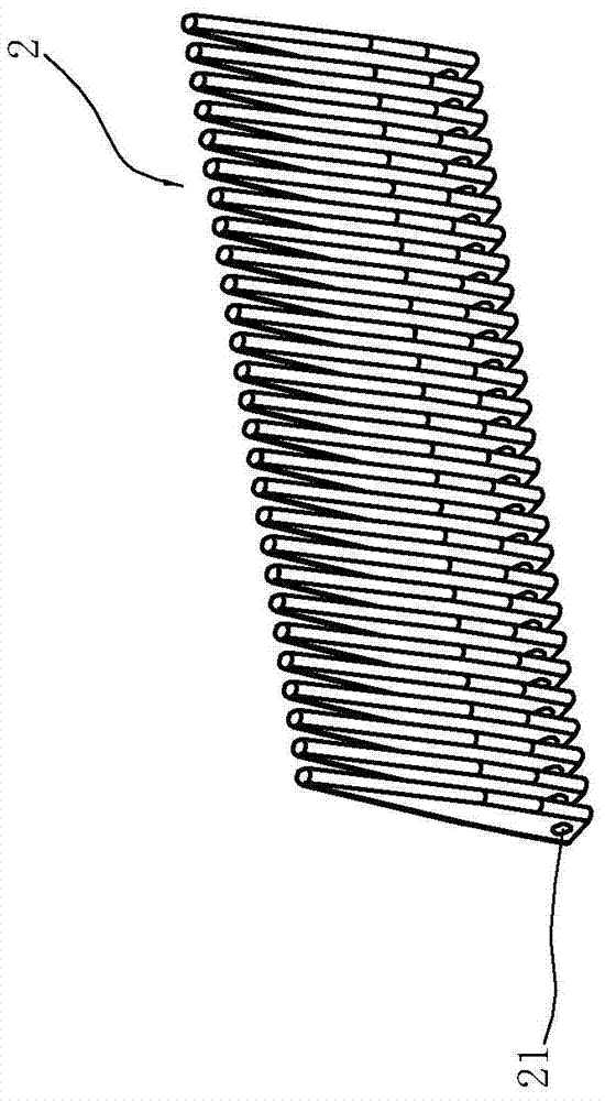
[0023] Combing needles 2, and each combing needle 2 is an independent single structure, and the root of each combing needle is provided with a through hole 21. In this embodiment, each combing needle 2 is a flat plate structure, and the root of each combing needle is roughly rectangular , the remaining part is roughly triangular, and the end of the comb needle is a smooth round head, and the width of the base of the comb needle is greater than the width of the comb needle exposed to the connecting seat.

[0024] The connection seat 3 is made of silica gel material, and includes a base 32 ...

Embodiment 2

[0031] Such as Figure 5 As shown, the elastic flat comb includes:

[0032] The base plate 4 is made of wood material or other materials, and the tail end of the base plate is extended to form a handle 42 for the operator to hold. A groove 41 is formed on the surface of the base plate 4 connected with the connecting base 6 . In this embodiment, the groove 41 is rectangular.

[0033] Combing needles 5, and each combing needle 5 is an independent single structure, and the root of each combing needle is provided with a through hole 51. In the present embodiment, each combing needle 5 is a flat plate structure, and the root of each combing needle is roughly rectangular , the remaining part is roughly triangular, and the end of the comb needle is a smooth round head, and the width of the base of the comb needle is greater than the width of the comb needle exposed to the connecting seat.

[0034] The connecting seat 6 is made of silica gel material, including a base 62 and an ins...


PUM


Abstract

The invention relates to an elastic flat comb which comprises a base plate and a plurality of comb teeth, and is characterized in that a flexible connecting seat is mounted on the base plate, and a plurality of slots are formed in the connecting seat at an interval and arranged in a row in the length direction of the connecting seat; the comb teeth are in independent single structures, the roots of the comb teeth are inserted into the corresponding slots, and the rest parts of the comb teeth are exposed on the connecting seat; through holes are formed in the roots of the comb teeth; a connecting rod is arranged between the through holes of the comb teeth and the slots in a penetration manner to further limit the relative positions of the comb teeth and the slots. According to the elastic flat comb, a traditional concept in the prior art is broken through; the comb teeth are separately designed and matched with the flexible connecting seat, so that the comb teeth can move in a three-dimensional direction under the action of an external force and better adapt to the head structure of a human body, and the combing process is more comfortable and healthier; due to the design of a single comb tooth combination structure, the comb tooth can be prepared from very small materials, so that certain leftovers can be fully utilized to prepare the comb teeth, raw materials are saved, and the manufacturing cost is reduced.

Description

technical field [0001] The invention relates to the field of hair combs, in particular to an elastic flat comb. Background technique [0002] The flat comb is a traditional hair comb, which is also the most commonly used in our daily life. It includes a base plate and a plurality of comb needles connected to the base plate, and these comb needles are arranged in a row along the length direction of the base plate. The material of the flat comb is mostly wood or plastic, and its processing method is usually to directly process the whole wooden base material, carve out the comb teeth and the handle, and the whole wooden comb is one piece; the hair comb prepared in this way is inelastic, and The teeth of the comb are easy to break, and the wood is also prone to cracks. Or use plastic one-time injection molding. Plastic hair combs are not only prone to static electricity due to the material, but also because of the structure, although plastic has a certain material elasticity, ...

Claims


Application Information

Patent Timeline
Patent Type & Authority Patents(China)
IPC IPC(8): A45D24/04
Inventor 姚大球
Owner 姚大球
Why Eureka
Try Eureka