Sintering method of optical fiber preform and equipment thereof

A technology for optical fiber preforms and sintering equipment, which is applied in glass manufacturing equipment, manufacturing tools, etc., can solve the problems of inability to adjust temperature in real time and effectively control it.

Active Publication Date: 2014-04-23
ZHONGTIAN TECH ADVANCED MATERIALS CO LTD +2
View PDF6 Cites 16 Cited by
  • Summary
  • Abstract
  • Description
  • Claims
  • Application Information

AI Technical Summary

Problems solved by technology

The present invention can overcome the problem that the current technology cannot adjust the temperature in the sintering process in real time and effectively control the transparency of the preform, and proposes a method based on PID control technology to adjust the temperature in the sintering process in real time and effectively control the transparency of the preform The method and its equipment can effectively prevent the rod body from being opaque after sintering due to improper setting of the sintering temperature of the sintering furnace.

Method used


Image

  • Sintering method of optical fiber preform and equipment thereof

Examples


Embodiment 1

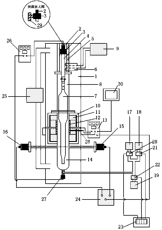
[0105] Set the temperature required for each stage on the temperature control cabinet 13, then install the powder preform 7 above the quartz suspender 4, send it into the furnace, and sinter according to the sintering method of the preform described above. A laser beam with a wavelength of 850nm and a power of 5.0mw is emitted from the laser transmitter 15, and the signal acquisition unit in the laser control cabinet 24 collects the laser power P' at the receiving end every 5s, and calculates the power difference ΔP =5mw-P'. Here, the upper limit value ΔPmax of ΔP is set to 4.5mw, and the lower limit value ΔPmin of ΔP is set to 3.5mw.

[0106] When the lower tail handle of the preform reaches the horizontal position of the laser, the laser senses the preform and enters the working state. When the ΔP value exceeds ΔPmax, the laser control cabinet sends a signal to the temperature control cabinet 13, requiring it to lower the furnace temperature by 10°C; when the ΔP value is lo...

Embodiment 2

[0108] Set the temperature required for each stage on the temperature control cabinet 13, then install the powder preform 7 above the quartz suspender 4, send it into the furnace, and sinter according to the sintering method of the preform described above. A laser beam with a wavelength of 850nm and a power of 5.0mw is emitted from the laser transmitter 15, and the signal acquisition unit in the laser control cabinet 24 collects the laser power P' at the receiving end every 5s, and calculates the power difference ΔP =5mw-P'. Here, the upper limit value ΔPmax of ΔP is set to 4.2mw, and the lower limit value ΔPmin of ΔP is set to 3.8mw.

[0109] When the lower tail handle of the preform reaches the horizontal position of the laser, the laser senses the preform and enters the working state. When the ΔP value exceeds ΔPmax, the laser control cabinet sends a signal to the temperature control cabinet 13, requiring it to lower the furnace temperature by 5°C; when the ΔP value is low...


PUM


Abstract

The invention relates to a sintering method of optical fiber preform and equipment thereof. The invention relates to the field of optical fiber perform sintering, and particularly relates to a method and equipment which utilize a laser feedback control system for adjusting the temperature of a sintering furnace in a sintering process in real time so as to realize the closed-loop control over the sintering process. The equipment comprises a tower body, a motor I, a chuck, a quartz derrick, a guide rail, a gas suction port, powder perform, a quartz chamber, a washing tower, a furnace body, a heat insulation material, a heating body, a temperature control cabinet, a quartz furnace core pipe, a laser transmitter, a laser receiver, a Cl2 gas holder, a He gas holder, an N2 gas holder, a Cl2 mass flow controller, a He mass flow controller, an N2 mass flow controller, an MFC (Microfunction Circuit) flow control cabinet, a laser control cabinet, an air exhaust and supply controller, a motor control cabinet, a motor II, a thermocouple, a lead screw and a control computer.

Description

technical field [0001] A method and equipment for sintering an optical fiber preform according to the present invention relate to the field of sintering an optical fiber preform, specifically, a laser feedback control system is used to adjust the temperature of the sintering furnace in real time during the sintering process, so as to realize the control of the sintering process. A method and device for closed-loop control. The method can be used to adjust the temperature of the sintering furnace in real time during the sintering process, so as to effectively control the transparency of the preform and prevent the preform from being opaque after sintering due to improper setting of the sintering temperature of the sintering furnace. Background technique [0002] At present, during the process of sintering the preform in the sintering furnace, its temperature is mainly controlled by a temperature controller. The temperature controller pre-sets several stages and assigns a con...

Claims


Application Information

Patent Timeline
Patent Type & Authority Applications(China)
IPC IPC(8): C03B37/012
Inventor 陶伟沈一春吴椿烽
Owner ZHONGTIAN TECH ADVANCED MATERIALS CO LTD
Why Eureka
Try Eureka