Al technical title is built by PatSnap Al team. It summarizes the technical point description of the patent document.
A composite clamp technology, which is applied in the direction of drill pipe, drilling equipment, earthwork drilling, etc., can solve the problems of large size, few applications, complex structure of normally closed swing rod clamp, etc.
Active Publication Date: 2014-05-28
XIAN RES INST OF CHINA COAL TECH& ENG GROUP CORP
View PDF8 Cites 5 Cited by
Summary
Abstract
Description
Claims
Application Information
AI Technical Summary
This helps you quickly interpret patents by identifying the three key elements:
Problems solved by technology
Method used
Benefits of technology
Problems solved by technology
Due to its complex structure and large size, the normally closed swing rod clamp is rarely used
Method used
Image
Click on the blue label to locate the original text in one second.
Reading with bidirectional positioning of images and text.
Examples
Embodiment Construction
[0031] The present invention will be described in detail below in conjunction with the accompanying drawings, so that the advantages and features of the present invention can be more easily understood by those skilled in the art, so as to define the protection scope of the present invention more clearly.
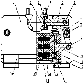
[0032] The invention relates to a double pendulum compound gripper, and the gripper adopts a strict left-right symmetrical design. see figure 1 . Including front baffle 1, lower slip block 2, upper slip block 3, screw rod 4, pressure rod 5, pressure rod pin 6, swing rod 7, swing rod pin 8, ejector pin 9, ejector rod 10. Side plate 11, tailgate 12, piston 13, elastic device 14, cylinder barrel 15 and base 16.
[0033] Wherein, the piston 13 and the cylinder barrel 15 form the booster cylinder cavity II, and the piston 13, the side plate 11 and the cylinder barrel 15 form the release cylinder cavity I.
[0034] The elastic device 14 is installed in the booster cylinder cham...
PUM
Abstract
The invention discloses a double pendulum rod compound holder, which comprises a front baffle, an upper slip segment, a lower slip segment, a lead screw, a compression bar, a compression bar pin roll, a pendulum rod, a pendulum rod pin roll, a mandril pin roll, a mandril, a side plate, a back baffle, a piston, elastic devices, a cylinder and a base. A force-applying device and a stress device of the double pendulum rod compound holder adopt the upper and lower double-layer design, and thus the size of the holder in the length direction is reduced. The left and right oil cylinders of the holder are internally provided with a set of elastic device respectively, pretightening force of the elastic devices are transmitted to the slip group by virtue of the lever principle, and thus a drill pipe is clamped. The power arm of a lever is larger than the resisting arm, so the holder has the function of increasing force. The slip group comprises the left and right slips, each slip is composed of the upper slip segment and the lower slip segment, and the slips are connected through the lead screw. Under the state that the holder clamps the drill pipe, the lead screw for connecting the slips is disassembled, the upper slip segment of each slip is removed, and thus the drill pipe is taken out. The double pendulum rod compound holder has a small external dimension and large opening, so the field use is facilitated.
Description
technical field [0001] The invention relates to a clamper for a drilling rig, in particular to a compound clamper with double swing rods, which is used for a full hydraulic drilling rig to clamp an in-hole drilling tool. Background technique [0002] The gripper has been widely used on various drilling rigs. Its function is to cooperate with the chuck to realize mechanical screwing and unloading of the drill pipe. It can also be used to clamp the drilling tool in the hole when drilling and tripping to prevent the drilling tool from slipping. There are many structures of the holder, the common ones are normally closed and normally open. [0003] The pendulum-type gripper is generally composed of a cross-type pendulum and an oil cylinder. Its working principle is similar to that of scissors, and the oil cylinder is its source of force. Generally, it is mostly used in normally open structure. Due to its complex structure and large size, the normally closed swing rod clamp is ...
Claims
Application Information
Patent Timeline
Application Date:The date an application was filed.
Publication Date:The date a patent or application was officially published.
First Publication Date:The earliest publication date of a patent with the same application number.
Issue Date:Publication date of the patent grant document.
PCT Entry Date:The Entry date of PCT National Phase.
Estimated Expiry Date:The statutory expiry date of a patent right according to the Patent Law, and it is the longest term of protection that the patent right can achieve without the termination of the patent right due to other reasons(Term extension factor has been taken into account ).
Invalid Date:Actual expiry date is based on effective date or publication date of legal transaction data of invalid patent.
Patent Type & Authority Applications(China)
IPC IPC(8): E21B19/10
Inventor 殷新胜刘智孙保山曹明
Owner XIAN RES INST OF CHINA COAL TECH& ENG GROUP CORP