Supercharge Your Innovation With Domain-Expert AI Agents!

Virtual antenna mapping method and device

A virtual antenna mapping and virtual antenna technology, applied in the field of communication, can solve the problems of unable to demodulate data, unable to achieve demodulation, etc.

Active Publication Date: 2014-06-25
HUAWEI TECH CO LTD
View PDF4 Cites 1 Cited by
  • Summary
  • Abstract
  • Description
  • Claims
  • Application Information

AI Technical Summary

Problems solved by technology

[0010] In this method, in highly correlated channels, that is, channels with uncertain phase differences between channels corresponding to different physical antennas, and the channel response of this channel is approximately H=[1 1 1 1], that is So when D is 1, and k=N FFT / 2, It is 0, that is, zero trap is generated, so the data received by the user side is 0, and demodulation cannot be realized, that is, the data cannot be demodulated due to the influence of zero trap

Method used


Image

  • Virtual antenna mapping method and device
  • Virtual antenna mapping method and device
  • Virtual antenna mapping method and device

Examples


Embodiment Construction

[0076] The following will clearly and completely describe the technical solutions in the embodiments of the present invention with reference to the accompanying drawings in the embodiments of the present invention. Obviously, the described embodiments are only some, not all, embodiments of the present invention. Based on the embodiments of the present invention, all other embodiments obtained by persons of ordinary skill in the art without creative efforts fall within the protection scope of the present invention.

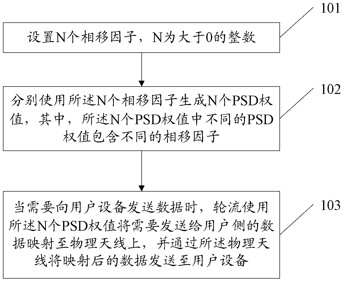
[0077] figure 1 is a schematic flowchart of a virtual antenna mapping method provided by an embodiment of the present invention, as shown in figure 1 shown, including:

[0078] 101. Set N phase shift factors, where N is an integer greater than 0;

[0079] 102. Use the N phase shift factors to generate N PSD weights respectively, where different PSD weights among the N PSD weights include different phase shift factors;

[0080] Optionally, step 102 may include: ...


PUM


Abstract

The embodiment of the invention discloses a virtual antenna mapping method. The method comprises the steps that N phase shift factors are set, and N is an integer greater than 0; N phase shift factors are respectively used to generate N PSD weights, wherein different PSD weights in N PSD weights comprise different phase shift factors; when data are sent to a user device, N PSD weights are used by turns to map the data which need to be sent to a user side to an physical antenna; and the mapped data are sent to the user device through the physical antenna. Correspondingly, the embodiment of the invention further discloses a network device. According to the embodiment of the invention, the influence of nulling on the user device can be reduced.

Description

technical field [0001] The present invention relates to the communication field, in particular to a virtual antenna mapping method and device. Background technique [0002] At present, Multiple-Input Multiple-Output (MIMO) technology is widely used. When this technology is applied, the number of physical channels actually used may exceed the number of antenna ports defined by the protocol. For example, the number of antenna ports defined by the protocol is 1. The antenna can be used in practical applications, and the use of the antenna requires the use of 2, 4 or 8 physical antenna ports; the protocol defines that the number of antenna ports is 2. The antenna can be used in practical applications, and the use of the antenna requires the use of 4 or 8 physical antenna ports Port; the protocol defines that an antenna with 4 antenna ports can be used in practical applications, and 8 physical antenna ports are required to use this antenna. In this case, one antenna port needs t...

Claims


Application Information

Patent Timeline
IPC IPC(8): H04B7/06
CPCH04B7/0617H04B7/06
Inventor 张松易雄书向涛刘云
Owner HUAWEI TECH CO LTD
Features
  • R&D
  • Intellectual Property
  • Life Sciences
  • Materials
  • Tech Scout
  • Unparalleled Data Quality
  • Higher Quality Content
  • 60% Fewer Hallucinations
Learn More