
Four-star voltage transformer secondary polarity intelligent tester
A technology of voltage transformer and secondary polarity, which is applied in the direction of electric winding testing, instrumentation, measuring electricity, etc., can solve problems such as low work efficiency, potential safety hazards, and high quality requirements, so as to improve work efficiency, reduce errors, and test fast and accurate results
- Summary
- Abstract
- Description
- Claims
- Application Information
AI Technical Summary
Problems solved by technology
Method used
Image

Examples
Embodiment Construction
[0019] The present invention will be further described in detail below in conjunction with the accompanying drawings and specific embodiments.
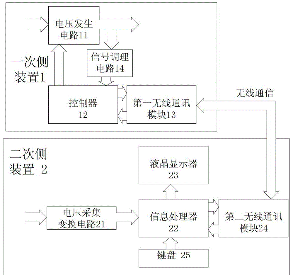
[0020] See figure 1 , The four-star voltage transformer secondary polarity intelligent tester of this embodiment is mainly composed of a primary side device 1, a secondary side device 2 and a power module. The power module is in figure 1 Not shown in the figure, the power module has a power output terminal; the power output terminal of the power module outputs +5V direct current, which is used as the working power of the system.
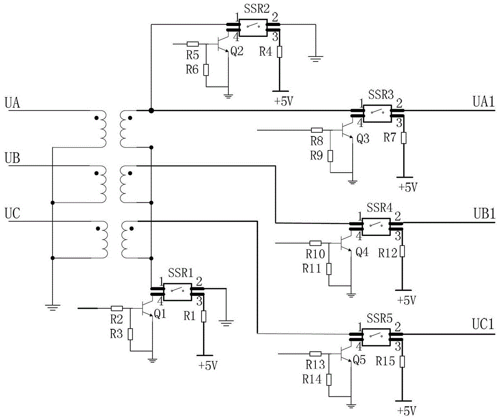
[0021] The primary device 1 is mainly composed of a voltage generating circuit 11 , a controller 12 , a first wireless communication module 13 and a signal conditioning circuit 14 . The voltage generating circuit 11 is provided with a voltage input terminal, a voltage output terminal, a drive signal input terminal and a power supply terminal; the controller 12 is provided with a first signal input termin...
PUM
 Abstract
Description
Claims
Application Information