Double-clutch lubricating structure for double-clutch gear box

A double-clutch, lubricating structure technology, applied in the direction of clutches, friction clutches, fluid-driven clutches, etc., can solve the problems of potential safety hazards, complex pipeline structure, low reliability, etc., and achieve high practical value, good safety, The effect of high reliability

Active Publication Date: 2014-09-24
NINGBO SHANGZHONGXIA AUTOMATIC TRANSMISSION
View PDF9 Cites 22 Cited by
  • Summary
  • Abstract
  • Description
  • Claims
  • Application Information

AI Technical Summary

Problems solved by technology

[0003] The purpose of the present invention is to provide a simple structure, high reliability and good safety to solve the problems of complex pipeline structure, high cost, low reliability and potential safety hazards in the existing dual clutch transmission cooling and lubrication system. Dual Clutch Lubrication Structure for Dual Clutch Transmission

Method used


Image

  • Double-clutch lubricating structure for double-clutch gear box
  • Double-clutch lubricating structure for double-clutch gear box
  • Double-clutch lubricating structure for double-clutch gear box

Examples


Embodiment 1

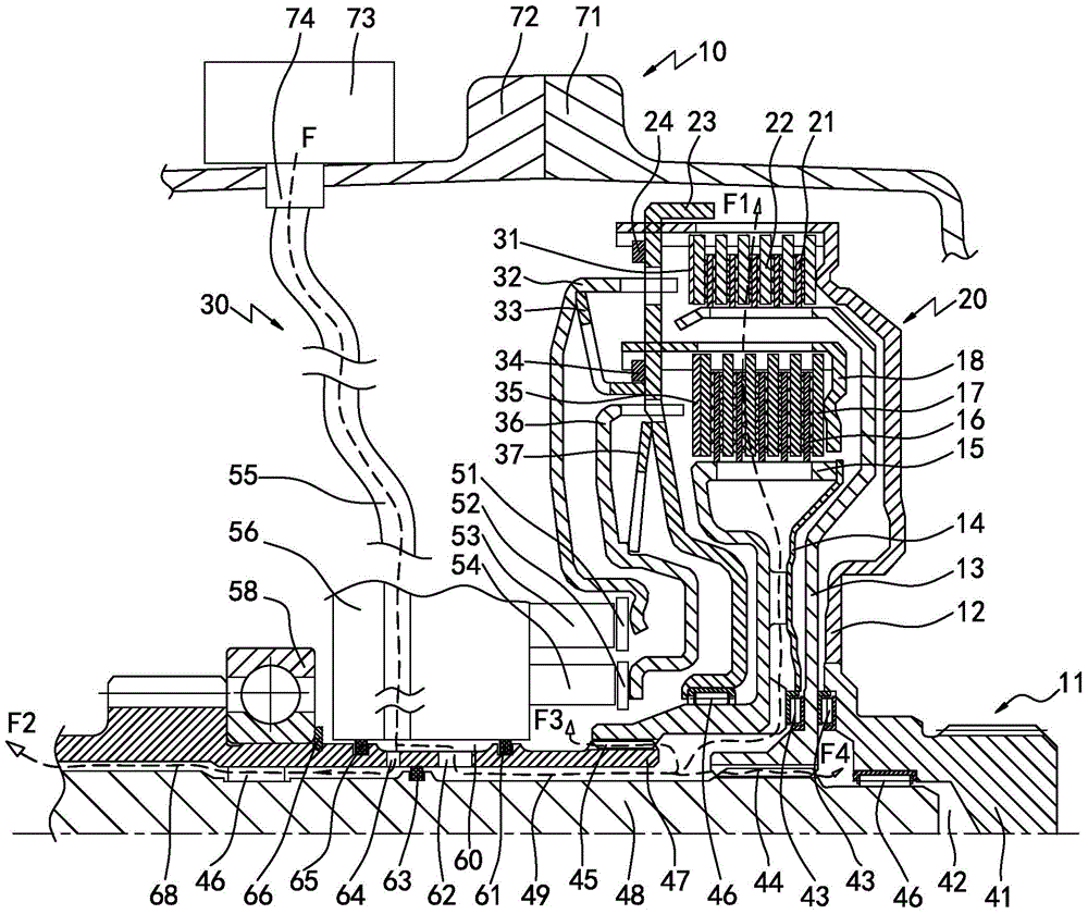
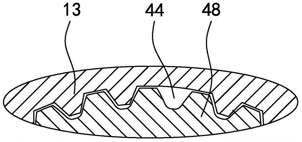
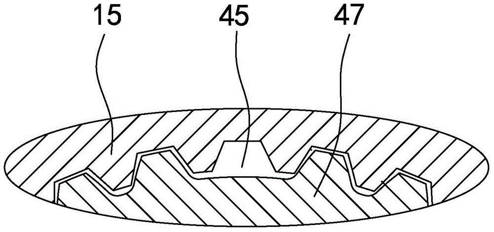
[0025] in such as figure 1 In the shown embodiment 1, a dual-clutch lubrication structure for a dual-clutch transmission is provided on a dual-clutch transmission 10, the dual-clutch transmission includes a dual-clutch 20 and an oil supply device 30, and the dual-clutch includes a The driving disc 12 connected to the driving device 11 is connected to the first input shaft 48 and the second input shaft 47 of the transmission. The first input shaft is connected, and the driving disc is connected with the second input shaft through the second clutch and the second clutch spline hub 15. It is characterized in that: the oil supply device includes an electronic oil pump 73, and the electronic oil pump is connected to the clutch through a lubricating oil pipe 55. Separation device 56, a closed oil storage chamber 60 is provided between the clutch separation device and the second input shaft, a lubricating oil passage is provided between the second input shaft and the first input shaf...

Embodiment 2

[0036] The front lubricating oil groove provided at the meshing place between the spline hub of the first clutch and the first input shaft in embodiment 2 is an axial groove between the two spline teeth on the outer spline of the first input shaft; the spline hub of the second clutch The rear lubricating oil groove set at the meshing place between the key hub and the second input shaft is an axial groove between two key teeth set on the external spline of the second input shaft (see image 3 ), and the rest are the same as in Example 1.

[0037]When the lubricating structure of the present invention works, the lubricating oil enters the oil storage chamber between the clutch separation device and the second input shaft from the electronic oil pump through the lubricating oil pipe, and the oil storage chamber passes through the front and rear oil holes on the second input shaft and four lubricating and cooling passages Connection, the lubricating oil in the first lubricating ch...


PUM


Abstract

The invention discloses a double-clutch lubricating structure for a double-clutch gear box. An electronic oil pump is connected with four lubricating channels through lubricating oil pipes and an oil storage cavity respectively, wherein the main components of the double-clutch, namely a first clutch and a second clutch, are lubricated and cooled by the lubricant liquid of the first lubricating channel; a first input shaft and a second input shaft of the double-clutch gear box are lubricated and cooled by the lubricant liquid of the second lubricating channel; a clutch separation device is lubricated and cooled by the lubricant liquid of the third lubricating channel; a bearing between the first input shaft and a driving device is lubricated and cooled by the lubricant liquid of the fourth lubricating channel. The double-clutch lubricating structure excellently solves the problem that a conventional cooling and lubricating system in a double-clutch gear box is complex in structure, high in cost and low in reliability, and is susceptible to potential safety hazard; the double-clutch lubricating structure provided by the invention is simple in structure, high in reliability and good in safety, and has very high practical value.

Description

technical field [0001] The invention relates to the technical field of automobile transmissions, in particular to a dual-clutch lubricating structure for an automobile dual-clutch transmission. Background technique [0002] With the increasing sales of automobiles and the continuous improvement of automobile power performance, the shifting performance of automobile transmissions has begun to receive more and more attention. With the development of the automobile industry, automatic transmissions have become a development trend, especially dual-clutch automatic transmissions. The dual-clutch automatic transmission realizes power shifting during the shifting process, that is, the power is not interrupted during the shifting process, which overcomes the shortcomings of AMT, solves the shortcomings of AMT shifting shock, and retains the good shifting quality of AT, CVT, etc. The advantage of this is that the power of the engine can always be transmitted to the wheels during the ...

Claims


Application Information

Patent Timeline
Patent Type & Authority Applications(China)
IPC IPC(8): F16H57/04
CPCF16D13/72F16D13/74F16H57/0412F16H57/0434F16H57/0454F16D21/06F16D25/08F16D25/10F16D25/123F16D2021/0661
Inventor 张新桂姚文博罗大国陈勇王瑞平
Owner NINGBO SHANGZHONGXIA AUTOMATIC TRANSMISSION
Why Eureka
Try Eureka