Gate drive system based on logic protection amplifying circuit

A technology of amplifying circuit and logic protection, applied in the field of LED drive circuit, can solve the problems of shortening startup time, long startup time, high current noise, etc., to avoid external electromagnetic interference, reduce current noise, and low power consumption.

Inactive Publication Date: 2015-03-11
CHENGDU COPOO TECH
View PDF0 Cites 1 Cited by
  • Summary
  • Abstract
  • Description
  • Claims
  • Application Information

AI Technical Summary

Problems solved by technology

[0003] The purpose of the present invention is to overcome the defects of high energy consumption, large current noise and long start-up time in the current gate drive circuit, and provide a reasonable structure design, which can effectively reduce power consumption and current noise, and significantly shorten the start-up time A gate drive system based on a logic protection amplifier circuit

Method used


Image

  • Gate drive system based on logic protection amplifying circuit
  • Gate drive system based on logic protection amplifying circuit

Examples


Embodiment

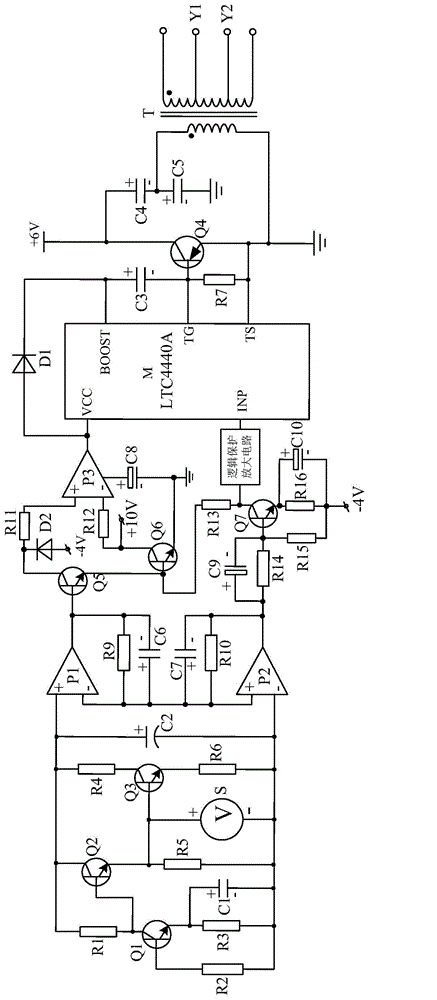
[0017] Such as figure 1 As shown, the present invention is composed of transistor Q4, transformer T, driver chip M, switching current source, diode D1, capacitor C3, resistor R7, capacitor C4, capacitor C5, switching power amplifying circuit, and logic protection amplifying circuit. When connecting, the output terminal of the switching current source needs to be connected with the input terminal of the switching power amplifying circuit, and the output terminal of the switching power amplifying circuit needs to be connected with the driving chip M. The diode D1 is connected in series between the VCC pin and the BOOST pin of the driving chip M to ensure that when the transformer T is damaged, its external current will not cause damage to the driving chip M. The capacitor C3 is connected in series between the BOOST pin and the TG pin of the driving chip M, and the resistor R7 is connected in series between the TG pin and the TS pin of the driving chip M.

[0018] The base of th...


PUM


Abstract

The invention discloses a gate drive system based on a logic protection amplifying circuit. The gate drive system mainly comprises a switch current source, a transformer T, a drive chip M, a diode D1, a capacitor C3 and a resistor R7, wherein the diode D1 is serially connected between a VCC pin and a BOOST pin of the drive chip M, the capacitor C3 is serially connected between the BOOST pin and a TG pin of the drive chip M, and the resistor R7 is serially connected between the TG pin and a TS pin of the drive chip M. The gate drive system is characterized in that the logic protection amplifying circuit is serially connected between the drive chip M and a switch power amplifying circuit. The gate drive system has the advantages that functions of short circuit protection, overvoltage protection and open circuit protection are realized, low power consumption is achieved, and starting time of the gate drive system is only 1 / 4 of that of a traditional gate drive circuit; moreover, owing to the switch power amplifying circuit, power signals inputted into the drive chip M can be guaranteed against attenuation so as to guarantee integral performance stability.

Description

technical field [0001] The invention relates to an LED drive circuit, in particular to a grid drive system based on a logic protection amplifier circuit. Background technique [0002] At present, due to the characteristics of low energy consumption, long service life, safety and environmental protection, LED lamps have become one of the mainstream products for people's living lighting. Since the LED lamp is different from the traditional incandescent lamp, it needs to be driven by a dedicated driving circuit. However, due to the unreasonable design structure of the currently widely used gate drive circuit, the current gate drive circuit has defects such as high energy consumption, large current noise, and long start-up time. Contents of the invention [0003] The purpose of the present invention is to overcome the defects of high energy consumption, large current noise and long start-up time in the current gate drive circuit, and provide a reasonable structure design, whi...

Claims


Application Information

Patent Timeline
Patent Type & Authority Applications(China)
IPC IPC(8): H05B37/02
CPCY02B20/40
Inventor 罗娅车容俊
Owner CHENGDU COPOO TECH
Why Eureka
Try Eureka