Wireless bridge with tool box

A technology of wireless network bridge and tool box, which is applied in wireless communication, network connection, electrical components, etc., can solve the problems of inconvenience of carrying a large number of tools, and the wireless network bridge does not have the function of storing maintenance tools.

Inactive Publication Date: 2015-03-18
XIAN HIGH TECH IND DEV ZONE WEST INFORMATION HARBOR
View PDF0 Cites 0 Cited by
  • Summary
  • Abstract
  • Description
  • Claims
  • Application Information

AI Technical Summary

Problems solved by technology

[0003] The purpose of the present invention is to overcome the problem that the outdoor wireless network bridge in the prior art does not have the function of storing maintenance tools, which makes it inconvenient for maintenance personnel to carry a large number of tools to work

Method used


Image

  • Wireless bridge with tool box
  • Wireless bridge with tool box
  • Wireless bridge with tool box

Examples


Embodiment 1

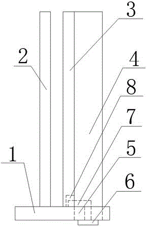
[0018] This embodiment provides a wireless network bridge with a tool box, including a base plate 1 and a circuit board 2, the right side of the circuit board 2 is provided with a tool box baffle 3, the tool box baffle 3 The right side is provided with tool box 4, and the lower end of described tool box 4 is provided with bottom surface baffle 5, and described bottom surface baffle 5 is nested in the base plate 1, and the lower surface of described bottom surface baffle 5 is provided with knob 6, so The knob 6 is connected with the catch 7 located on the upper surface of the bottom baffle 5 , the lower end of the tool box baffle 3 is fixed to the bottom plate 1 , and a groove 8 is provided within the rotation range of the catch 7 .

Embodiment 2

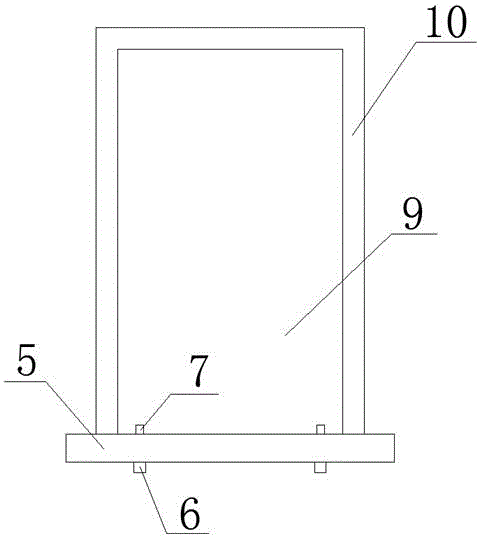
[0020] Such as figure 2 The side baffle 10 and the rear baffle 9 of the shown tool box 4 are fixed together, and are respectively provided with a plurality of small holes that can fix U-shaped cards, and the U-shaped cards are used to fix the tools placed in the tool box 4 , the maintenance personnel can choose the tool stored in the tool box 4 according to the actual needs. Since the tool box 4 is vertical, the U-shaped card can fix the tool without being messy. The position of the U-shaped card is set according to the different tools. Adjustable and flexible.

Embodiment 3

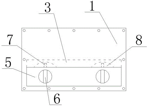
[0022] Such as figure 1 The shown knob 6 is connected to the blocking piece 7 through a threaded bolt, and the blocking piece 7 can be rotated synchronously by turning the knob 6. When a tool needs to be used for maintenance, the tool box can be opened to obtain the tool by turning the knob 6 .

[0023] Such as figure 2 and image 3 There are two knobs 6 shown, which are respectively arranged at positions on the left and right sides of the bottom baffle 5 close to the bottom baffle 5, so that the tool box 4 is fixed firmly.

[0024] Such as figure 2 The shown groove 8 is arc-shaped, and fits the rotation range of the blocking plate 7 , so that the groove 8 will not affect the stability of the tool box blocking plate 3 .


PUM


Abstract

The invention belongs to the communication equipment technical field and provides a wireless bridge with a tool box. The wireless bridge comprises a bottom plate (1) and a circuit board (2); a tool box baffle (3) is arranged at the right side of the circuit board (2); a tool box (4) is arranged at the right side of the tool box baffle (3); the lower end of the tool box (4) is provided with a bottom-surface baffle (5); the bottom-surface baffle (5) is nested in the bottom plate (1); the lower surface of the bottom-surface baffle (5) is provided with a knob (6); the knob (6) is connected with a stopping sheet (7) located at the upper surface of the bottom-surface baffle (5); the lower end of the tool box baffle (3) is fixed to the bottom plate (1) and is provided with a groove (8) in a rotation range of the stopping sheet (7). An outdoor wireless bridge in the prior art has no functions for accommodating repair tools, and as a result, repair personnel should carry a large number of tools, and are inconvenient to work, while, with the wireless bridge of the invention adopted, the above situation in the prior art can be avoided. The wireless bridge is advantageous in that the wireless bridge can accommodate repair tools.

Description

technical field [0001] The invention belongs to the technical field of communication equipment, and in particular relates to a wireless network bridge with a tool box. Background technique [0002] Existing wireless bridges are mostly used for engineering erection, and are often installed outdoors. When affected by factors such as weather, they are prone to failure. Maintenance personnel often have to carry a large number of tools to repair, which is very inconvenient. Contents of the invention [0003] The purpose of the present invention is to overcome the problem that the outdoor wireless network bridge in the prior art does not have the function of storing maintenance tools, which makes it inconvenient for maintenance personnel to carry a large number of tools to work. [0004] For this reason, the present invention provides a kind of wireless network bridge with tool box, comprises base plate and circuit board, and the right side position of described circuit board is...

Claims


Application Information

Patent Timeline
IPC IPC(8): H04L12/66H04W88/02
Inventor 杨玉山
Owner XIAN HIGH TECH IND DEV ZONE WEST INFORMATION HARBOR
Why Eureka
Try Eureka