Edge circuit, array substrate and display panel

A circuit and edge technology, applied in the display field, can solve problems affecting the display effect of the display panel

Active Publication Date: 2015-03-25
XIAMEN TIANMA MICRO ELECTRONICS +1
View PDF3 Cites 8 Cited by
  • Summary
  • Abstract
  • Description
  • Claims
  • Application Information

AI Technical Summary

Problems solved by technology

[0003] In view of this, the present invention provides an edge circuit, an array substrate and a display panel to solve the problem in the prior art that the picture display effect of the display panel is affected due to a large amount of residual charge

Method used


Image

  • Edge circuit, array substrate and display panel
  • Edge circuit, array substrate and display panel
  • Edge circuit, array substrate and display panel

Examples


Embodiment Construction

[0017] The following will clearly and completely describe the technical solutions in the embodiments of the present invention with reference to the accompanying drawings in the embodiments of the present invention. Obviously, the described embodiments are only some, not all, embodiments of the present invention. Based on the embodiments of the present invention, all other embodiments obtained by persons of ordinary skill in the art without making creative efforts belong to the protection scope of the present invention.

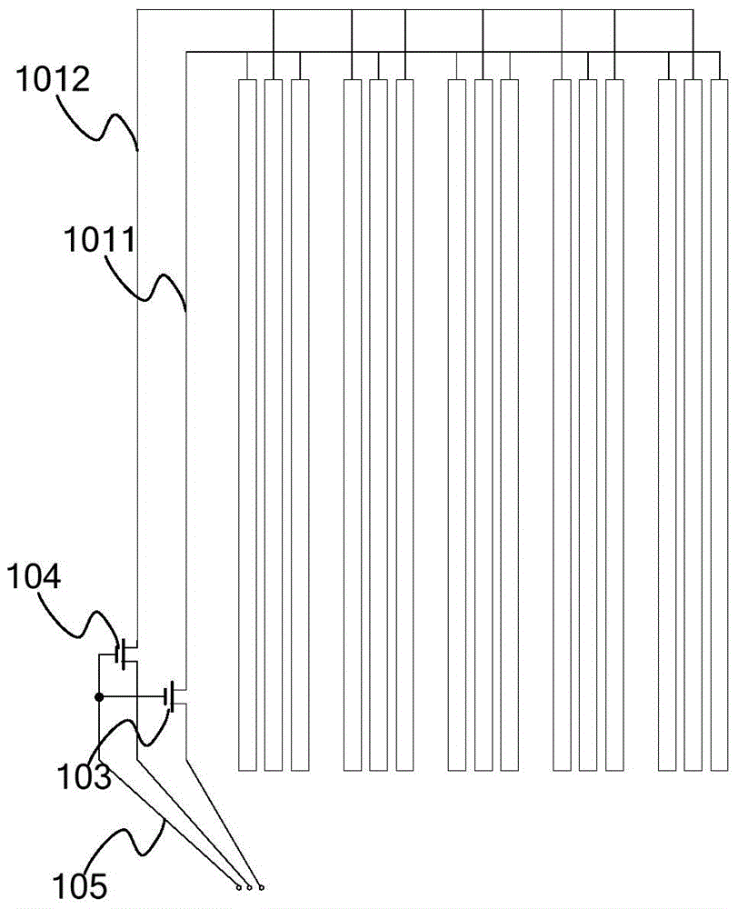
[0018] As mentioned in the background art, after the existing test circuit finishes the test, a large amount of charge will remain in the data line, which will affect the display effect of the picture. The structure of the test circuit is as figure 1 As shown, it includes a first lead 1011 connected to all odd column data lines, a second lead 1012 connected to all even column data lines, a source connected to the first lead 1011 and a drain connected to the fl...


PUM


Abstract

The invention provides an edge circuit, an array substrate and a display panel. The edge circuit comprises a plurality of first switches, at least one second switch and at least one testing end, wherein the control ends of the first switches are electrically connected with a first control line, the control end of each second switch is electrically connected with a second control line, the output ends of the first switches are electrically connected with at least one data line, the input end of each first switch is electrically connected with the output end of one second switch and one testing end, and the input end of each second switch is connected with a low level or earth electricity. Thus, the first switches can be controlled to be turned on or off through the first control line and the second switches can be controlled to be turned on or off through the second control line so that the data lines can be tested or charges remaining in the data lines can be removed, and the problem that because a large number of charges remain, the image display effect of the display panel is affect is solved.

Description

technical field [0001] The present invention relates to the field of display technology, and more specifically, to an edge circuit, an array substrate and a display panel. Background technique [0002] During the manufacturing process of the display panel, it is necessary to continuously test the gate lines, data lines, common electrode lines, etc., so as to ensure the quality and performance of the display panel. An existing testing method is to form a test circuit around the array substrate while manufacturing the array substrate, test the circuit to be tested through the test circuit, and then remove the test circuit after the test is completed, and continue the subsequent manufacturing process. However, after the data line is tested and the display panel is working, since a large amount of charge remains on the data line, the image display effect of the display panel will be affected. Contents of the invention [0003] In view of this, the present invention provides ...

Claims


Application Information

Patent Timeline
Patent Type & Authority Applications(China)
IPC IPC(8): G02F1/1362
CPCG02F1/1362G09G3/006G02F1/136254
Inventor 郑志伟杨康鹏许育民
Owner XIAMEN TIANMA MICRO ELECTRONICS
Why Eureka
Try Eureka