

Leading-edge slat with drainage groove and designing method of drainage groove
A leading-edge slat and drainage groove technology, which is applied in the direction of affecting the airflow flowing through the surface of the aircraft, wings, aircraft parts, etc., can solve the problems that cannot well meet the flow control needs of the aircraft's leading-edge slat
- Summary
- Abstract
- Description
- Claims
- Application Information
AI Technical Summary
Problems solved by technology
Method used
Image

Examples
Embodiment Construction
[0156] The present invention will be described in further detail below in conjunction with the accompanying drawings.
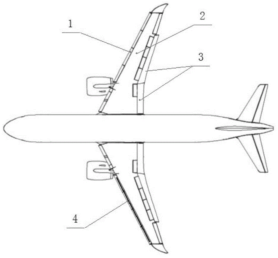
[0157] as attached figure 1 As shown, the aircraft adopts the combination mode of leading edge slat 1, main wing section 2 and trailing edge flap 3 during takeoff / landing to obtain high lift required for takeoff / landing.
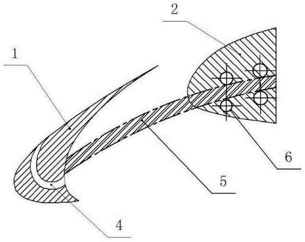
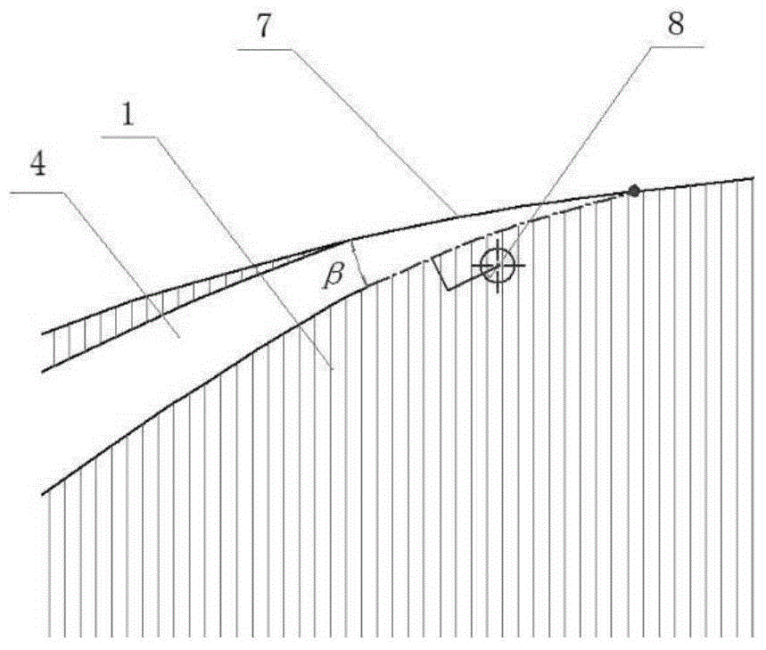
[0158] as attached Figure 4 ~As shown in accompanying drawing 6, the leading edge slat of prior art is made up of inner and outer two sections, is positioned at wing leading edge and distributes along span. The slat drainage groove described in this embodiment is located on the outer section of the slat and runs through the upper surface and the lower surface of the section of the slat; Spread distribution.
[0159] The drainage slot for improving the stall characteristics of the aircraft described in this embodiment is located on the leading edge slat 1 of the combined mode, as attached figure 1 , attached figure 2 shown.
[0160] ...
PUM
 Abstract
Description
Claims
Application Information