Positionable infrared paintbrush and positioning method thereof

A calligraphy and painting brush and infrared technology, applied in the field of image processing, can solve problems such as uncontrollable pen down and pen up, out of shape, etc.

CN104635960AActive Publication Date: 2015-05-20INLIFE HANDNET CO LTD
7 Cites 1 Cited by

Patent Information

Authority / Receiving Office
CN · China
Patent Type
Applications(China)
Current Assignee / Owner
Publication Date
2015-05-20

Smart Images

  • Figure 1
    Figure 1
  • Figure 2
    Figure 2
  • Figure 3
    Figure 3
Patent Text Reader

Abstract

The invention discloses a positionable infrared paintbrush and a positioning method thereof. The paintbrush comprises a paintbrush body (10), an infrared light source component (30) and a nib (20), the infrared light source component (30) is accommodated in the paintbrush body (10), the nib (20) is arranged at one end of the paintbrush body (10) and used for transmitting infrared light emitted by the infrared light source component (30) out of the paintbrush body (10), a plurality of infrared light emitting mechanisms (70) used for emitting the infrared light are arranged at one end, close to the nib (20), of the paintbrush body (10) so as to position the spatial position of the infrared paintbrush, the infrared light emitting mechanisms (70) are evenly distributed along the circumferential outer wall of the paintbrush body (10), the direction of the infrared light emitted by each infrared light emitting mechanism (70) on one side, facing the nib (20) is identical to that of the included angle of the axis of the paintbrush body (10), and the included angles are acute angles, so that the spatial position of the infrared paintbrush can be positioned according to incident points projected on a painting board by the infrared light emitting mechanisms, inclination of the paintbrush and distance between the tip of the nip and the painting board are judged, and first strokes and last strokes are effectively simulated.
Need to check novelty before this filing date? Find Prior Art

Description

technical field

[0001] The invention relates to the field of image processing, and more specifically relates to a positionable infrared calligraphy and painting brush and a positioning method thereof. Background technique

[0002] The infrared calligraphy and painting pen in the prior art uses optical fiber to make the nib. The nib has certain flexibility and can simulate the effect of a writing brush and a paintbrush. By collecting the infrared light image of the pen to track the running track of the pen, it simulates calligraphy and painting handwriting. It is very important to start and close the pen when doing calligraphy and painting. Because this kind of infrared calligraphy and painting pen adopts the principle of active light emission, when the pen tip is not in contact with the painting and calligraphy panel, the infrared light emitted by the pen is sensed. When the pen tip leaves the calligraphy and painting board, The infrared sensor does not detect it immediately...

Examples

Embodiment 1

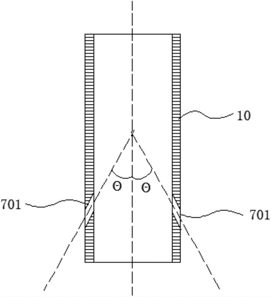
[0043] refer to figure 2 , is a schematic cross-sectional structure diagram of the first embodiment of the infrared calligraphy and painting brush of the present invention;

[0044] In this embodiment, the infrared light emitted by the existing infrared light source assembly 30 inside the pen body 10 is used for positioning. Specifically, the infrared light source assembly 30 is located on the central axis of the pen body 10, and the infrared light emission mechanism 70 includes an infrared light that penetrates the side wall of the pen body 10 and is used to emit infrared light from the infrared light source assembly 30. For the transmitted light holes 701 , the extension direction of each light hole 701 has the same angle with the axis of the pen body 10 on the side facing the pen head 20 , and the included angle is an acute angle.

[0045] In this embodiment, the infrared light emitted by the infrared light source assembly 30 is transmitted from each light hole 701. Since...

Embodiment 2

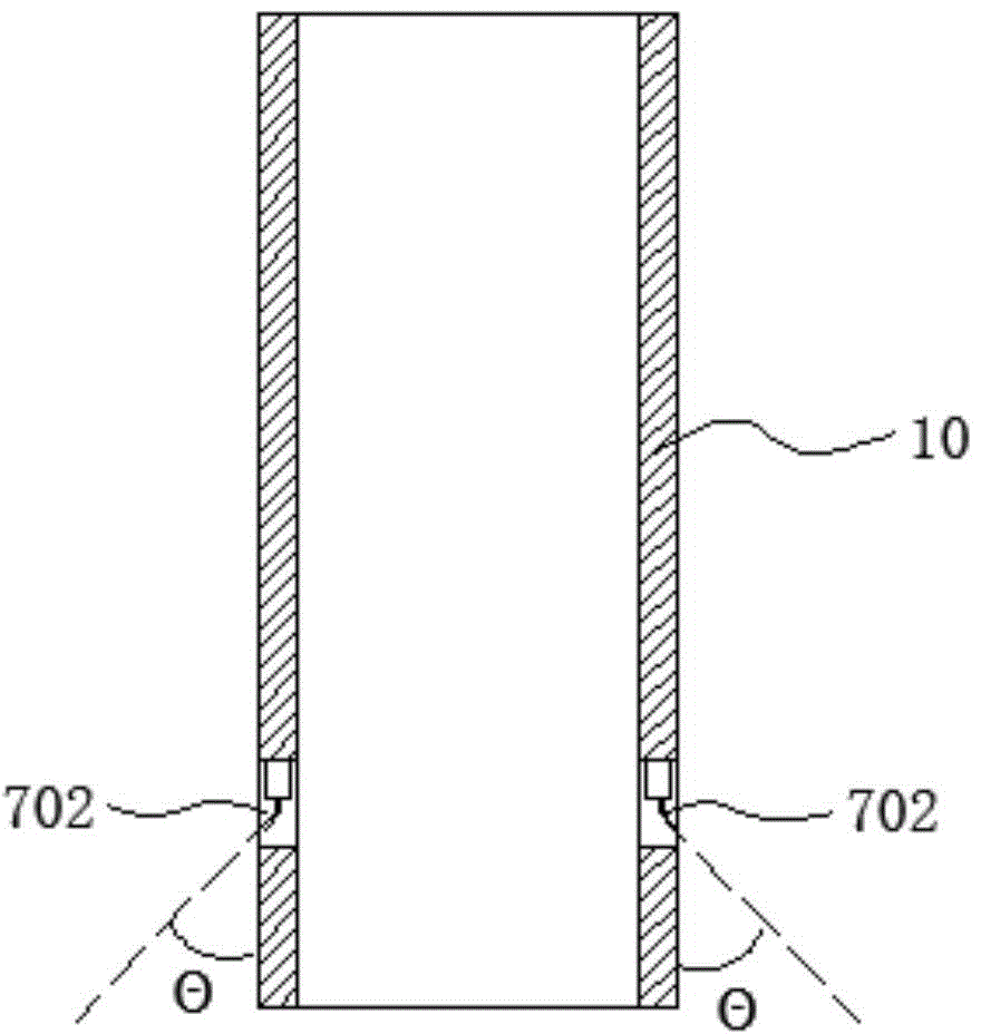
[0049] refer to image 3 , is a schematic cross-sectional structure diagram of the second embodiment of the infrared calligraphy and painting brush of the present invention;

[0050] The infrared light emitting mechanism 70 includes: installation holes 702 opened on the side wall of the pen body 10 and infrared LED lamps fixed in the corresponding installation holes 702 . The opening of the installation hole 702 is not limited, as long as it can provide a space for fixing the infrared LED lamp. Of course, it is understandable that the infrared LED light can also be directly fixed on the outer wall of the pen body 10, as long as the infrared light can be emitted uniformly at the same angle and at the same height.

[0051] In this embodiment, considering the wiring arrangement of the infrared LED lamp, the installation hole 702 is specifically a through hole with a square cross section radially penetrating through the side wall of the pen body 10, and the infrared LED lamp can ...