

Electric and spring coupling pressure foot and control method of automatic hole-making end effector
An end effector, spring coupling technology, applied in the direction of manufacturing tools, clamping, support, etc., can solve the problem that the pressure foot cannot stably maintain the pressure state, the pneumatic control system does not have high output stiffness, and the overall quality of the end effector is high. Achieve significant vibration absorption effect, good vibration absorption effect, and good pressure control stability.
- Summary
- Abstract
- Description
- Claims
- Application Information
AI Technical Summary
Problems solved by technology
Method used
Image

Examples
Embodiment Construction
[0028] The present invention will be further described below in conjunction with the accompanying drawings:
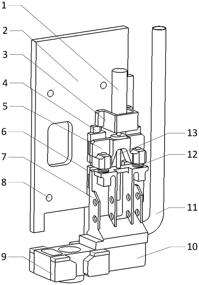
[0029] like figure 1 The motorized and spring-coupled pressure feet of the automatic hole-making end effector shown are mounted on the spindle base plate 2 on which the hole-making spindle is mounted, and the spindle base plate 2 is screwed to the inner cross of the end effector through threaded holes 8 On the sliding table, the hole-making spindle feeds with the movement of the spindle base plate 2 on the cross sliding table, and is characterized in that: the pressure foot includes a pressure script body and a pressure foot servo system, and the pressure script body is connected to the pressure foot through the pressure foot connecting seat 7 The base 10, the pressure foot connecting seat 7 is installed on the guide rail 4 on the main shaft base plate 2 through the slider 6; the pressure foot servo system includes a servo motor 1, a host computer that controls the ser...
PUM
 Abstract
Description
Claims
Application Information