Method, device and system for flow equalization

A current and average technology, applied in the electronic field, can solve problems such as high cost, increased volume and cost, and affecting system efficiency

Active Publication Date: 2015-05-27
HUAWEI DIGITAL POWER TECH CO LTD +1
View PDF5 Cites 4 Cited by
  • Summary
  • Abstract
  • Description
  • Claims
  • Application Information

AI Technical Summary

Problems solved by technology

[0006] In the above-mentioned process of realizing current sharing, the inventors found that there are at least the following problems in the prior art: on the one hand, the scheme of resistor current sharing increases extra loss due to resistance heating, which affects system efficiency and wastes energy; on the other hand , using the inductor current sharing scheme, due to the large volume and high cost of the inductor, the volume and cost are increased

Method used


Image

  • Method, device and system for flow equalization
  • Method, device and system for flow equalization
  • Method, device and system for flow equalization

Examples


Embodiment 1

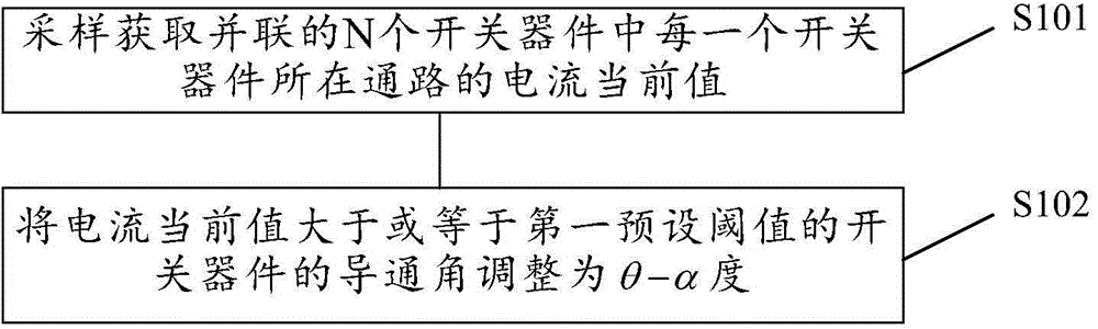
[0063] Embodiment 1 of the present invention provides a flow equalization method, such as figure 1 As shown, the method may include:

[0064] S101. Sampling and obtaining the current current value of the path where each switching device is located in the N switching devices connected in parallel;

[0065] Wherein, sampling devices (for example: current transformers, sampling resistors, etc.) can be respectively set in the path of each switching device in the N switching devices in parallel, and the path of each switching device in the N switching devices in parallel can be respectively sampled and obtained. The current value of the current;

[0066] Optionally, it may also be realized by adopting a centralized sampling method, for example, digital signal processing technology (digital signal processing, DSP for short), to obtain the current current value of the path where each switching device of the N switching devices connected in parallel is obtained through centralized sa...

Embodiment 2

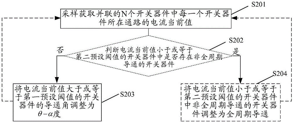
[0103] Embodiment 2 of the present invention provides a flow equalization method, such as figure 2 As shown, the method may include:

[0104] S201. Sampling and acquiring the current current value of the path where each switching device of the N switching devices connected in parallel is located;

[0105] Specifically, the specific manner of sampling and acquiring the current current value of the path where each switching device is located in the parallel N switching devices has been described in detail in Embodiment 1, and will not be repeated here.

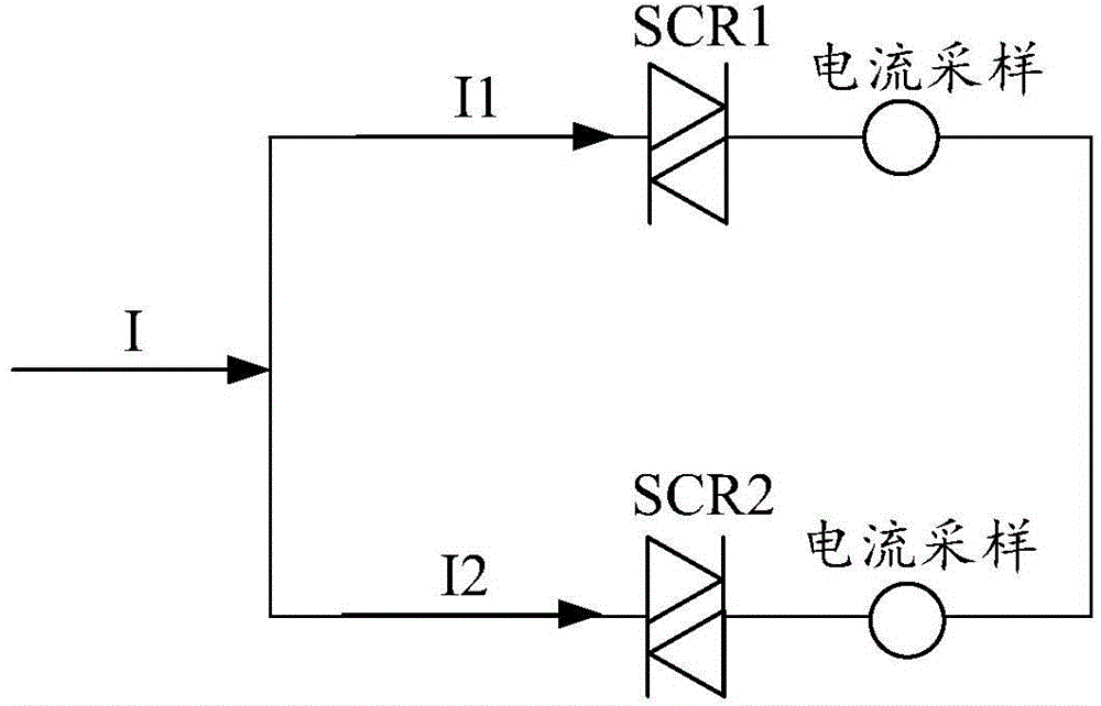
[0106] Exemplary, with image 3 Take the circuit shown as an example. The circuit includes two parallel SCRs, namely SCR1 and SCR2. The load of this circuit is a resistive load. The sampling resistor is set in the circuit to sample and obtain the current current value of the channel where the parallel SCR is located;

[0107] Such as Figure 4 As shown, both SCR1 and SCR2 are turned on in a full cycle, and the current condu...

Embodiment 3

[0135] Embodiment 3 of the present invention provides a current equalizing device 90, such as Figure 9 As shown, the current equalizing device 90 may include:

[0136] The sampling unit 901 is used to sample and obtain the current current value of the path where each switching device is located in the N switching devices connected in parallel;

[0137] The first adjustment unit 902 is configured to adjust the conduction angle of the switching device whose current current value is greater than or equal to the first preset threshold value to θ-α degrees; wherein, the θ means that the current current value is greater than or equal to the first preset threshold Threshold is the current conduction angle of the switching device; the α is greater than zero.

[0138] Further, see Figure 10 , the current equalizing device 90 may also include:

[0139] A judging unit 903, configured to judge whether there is a non-full-period conduction switching device among the switching devices ...


PUM


Abstract

The embodiment of the invention discloses a method, device and system for flow equalization, and relates to the field of electronics. Through the use of the method, device and system, flow equalization of which the volume, the cost and the extra loss are not increased is realized. The technical scheme adopted by the method comprises the following steps: through sampling, obtaining a present current value of a passage of each switching device in N switching devices which are connected in parallel; regulating a conduction angle of the switching device of which the present current value is greater than or equal to a first preset threshold value to a theta-alpha degree, wherein theta is the present conduction angle of the switching device of which the present current value is greater than or equal to the first preset threshold value, and alpha is greater than 0. The method, device and system disclosed by the invention are used for the flow equalization of the switching devices.

Description

technical field [0001] The present invention relates to the field of electronics, in particular to a current sharing method, device and system. Background technique [0002] The current grid power supply cannot guarantee the quality of the power grid, so it cannot provide the clean and stable power supply required by sensitive electronic equipment; due to the quality problems of the grid itself, various accidental factors, natural disasters, etc. Surge, electromagnetic noise, continuous high voltage, continuous low voltage, etc.) occur frequently, and may even cause long-term power outages, resulting in data loss of electrical equipment. Therefore, Uninterruptible Power System (UPS for short) came into being. [0003] UPS is a device that can take over from the mains to continuously supply power when there is a power outage, and continue to supply power when the mains power is abnormal or when there is a power outage, ensuring the safety and reliability of electricity for cu...

Claims


Application Information

Patent Timeline
IPC IPC(8): H02J9/00
Inventor 张春涛
Owner HUAWEI DIGITAL POWER TECH CO LTD
Why Eureka
Try Eureka