
A branch track mechanism for sorting on both sides of a linear sorter and its application method

A sorter, fork road technology, applied in the direction of sorting, conveyor objects, transportation and packaging, etc., can solve the problems of limited number of sorting outlets, reduce the types of parcel sorting and work efficiency, and achieve important application value, sorting and other problems. The effect of picking type improvement

Active Publication Date: 2016-03-02
苏州九鲤机电科技有限公司
View PDF6 Cites 0 Cited by
  • Summary
  • Abstract
  • Description
  • Claims
  • Application Information

AI Technical Summary

Problems solved by technology

[0002] Existing linear sorting machines generally adopt single-side sorting technology, that is, the parcels enter from the entrance of the linear sorting machine and only flow out from one side of the linear sorting machine, so that within the effective sorting length, the sorting exit The quantity is extremely limited, which greatly reduces the sorting types and work efficiency of parcels

Method used


Image

  • A branch track mechanism for sorting on both sides of a linear sorter and its application method
  • A branch track mechanism for sorting on both sides of a linear sorter and its application method
  • A branch track mechanism for sorting on both sides of a linear sorter and its application method

Examples


Embodiment 1

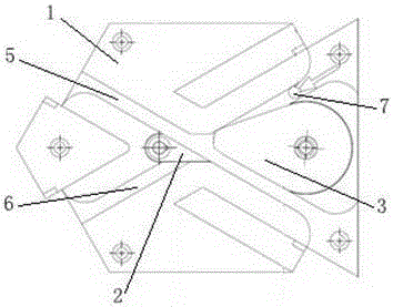
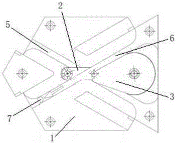
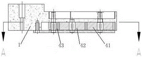
[0023] refer to figure 1 , figure 2 , image 3 with Figure 4 In this embodiment, a branch mechanism for sorting on both sides of a linear sorter includes a branch plate 1, a driven fork 2, an active fork 3 and a transmission mechanism 4, and the upper end surfaces of the branch plate 1 are connected to each other. The first guide groove 5 and the second guide groove 6 are arranged crosswise, the driven fork 2 and the active fork 3 are respectively rotated and arranged on the upper end surface of the diverge plate 1 through the rotating shaft, and the active fork 3 is driven by the transmission mechanism 4 The moving fork 2 swings on the branch board 1 in the same direction (the bottom of the branch board 1 is provided with a groove, and the transmission mechanism 4 is set in the groove), and the active fork 3 swings to close any one of the guide grooves. When there is one guide slot at the intersection, the driven fork 2 closes the guide slot at the other guide slot at th...

Embodiment 2

[0029] refer to figure 1 , figure 2 , Figure 5 with Image 6 , a branch track mechanism for sorting on both sides of a linear sorter described in this embodiment, including:

[0030] The branch plate 1, the driven fork 2, the driving fork 3 and the transmission mechanism 4, the upper end surface of the branch plate 1 are provided with the first guide groove 5 and the second guide groove 6 intersecting each other, the driven fork 2 and the driving fork The forks 3 are respectively rotated and arranged on the upper end surface of the diverge plate 1 through the rotating shaft, and the active forks 3 drive the driven forks 2 to swing in the same direction on the diverge plate 1 through the transmission mechanism 4 (the bottom of the diverge plate 1 is provided with a concave slot, the transmission mechanism 4 is set in the groove), and when the active fork 3 swings to close any one of the guide slots at the intersection, the driven fork 2 closes the guide slot at the interse...


PUM


Abstract

The invention provides a turnoff mechanism for sorting on two sides of a linear sorting machine, and a use method of the turnoff mechanism. The turnoff mechanism comprises a turnoff plate, a driven shifting fork, a drive shifting fork and a transmission mechanism, wherein the turnoff plate is provided with a first guide groove and a second guide groove which are mutually cross; the drive shifting fork drives the driven shifting fork to swing on the turnoff plate by the transmission mechanism, and when the drive shifting fork swings to seal a guide groove opening, at a crossing, of any one of the guide grooves, the driven shifting fork seals another guide groove opening, at the crossing, of the guide groove. Under the condition that mutual noninterference is ensured, sorting on two sides of the linear sorting machine is realized. The invention belongs to the field of sorting.

Description

technical field [0001] The invention relates to a branching mechanism, which belongs to the field of sorting. Background technique [0002] Existing linear sorting machines generally adopt single-side sorting technology, that is, the parcels enter from the entrance of the linear sorting machine and only flow out from one side of the linear sorting machine, so that within the effective sorting length, the sorting exit The quantity is extremely limited, which greatly reduces the sorting types and work efficiency of parcels. If sorting ports can be arranged on both sides of the linear sorting machine, the sorting types of parcels will be doubled, which will greatly improve the working efficiency of the sorting machine and effectively save the occupation of sorting equipment. land area. Contents of the invention [0003] The purpose of the present invention is to provide a branch track mechanism for sorting on both sides of a linear sorter and its use method, so as to realiz...

Claims


Application Information

Patent Timeline
Patent Type & Authority Patents(China)
IPC IPC(8): B65G47/74B07C3/06
Inventor 陈云鹏张卫华陈义强陈天崚
Owner 苏州九鲤机电科技有限公司
Learn More