Difference slit MIMO (Multiple Input Multiple Output) antenna with high common mode rejection ratio

A high common-mode suppression and slot technology, which is applied to antennas, devices that make antennas work in different frequency bands at the same time, and radiating element structures, etc. The effect of high common mode rejection ratio

Active Publication Date: 2015-09-02
SOUTH CHINA UNIV OF TECH
View PDF4 Cites 13 Cited by
  • Summary
  • Abstract
  • Description
  • Claims
  • Application Information

AI Technical Summary

Problems solved by technology

But compared with differential antennas, there is no suppression of common mode

Method used


Image

  • Difference slit MIMO (Multiple Input Multiple Output) antenna with high common mode rejection ratio
  • Difference slit MIMO (Multiple Input Multiple Output) antenna with high common mode rejection ratio
  • Difference slit MIMO (Multiple Input Multiple Output) antenna with high common mode rejection ratio

Examples


Embodiment 1

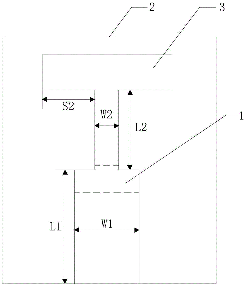
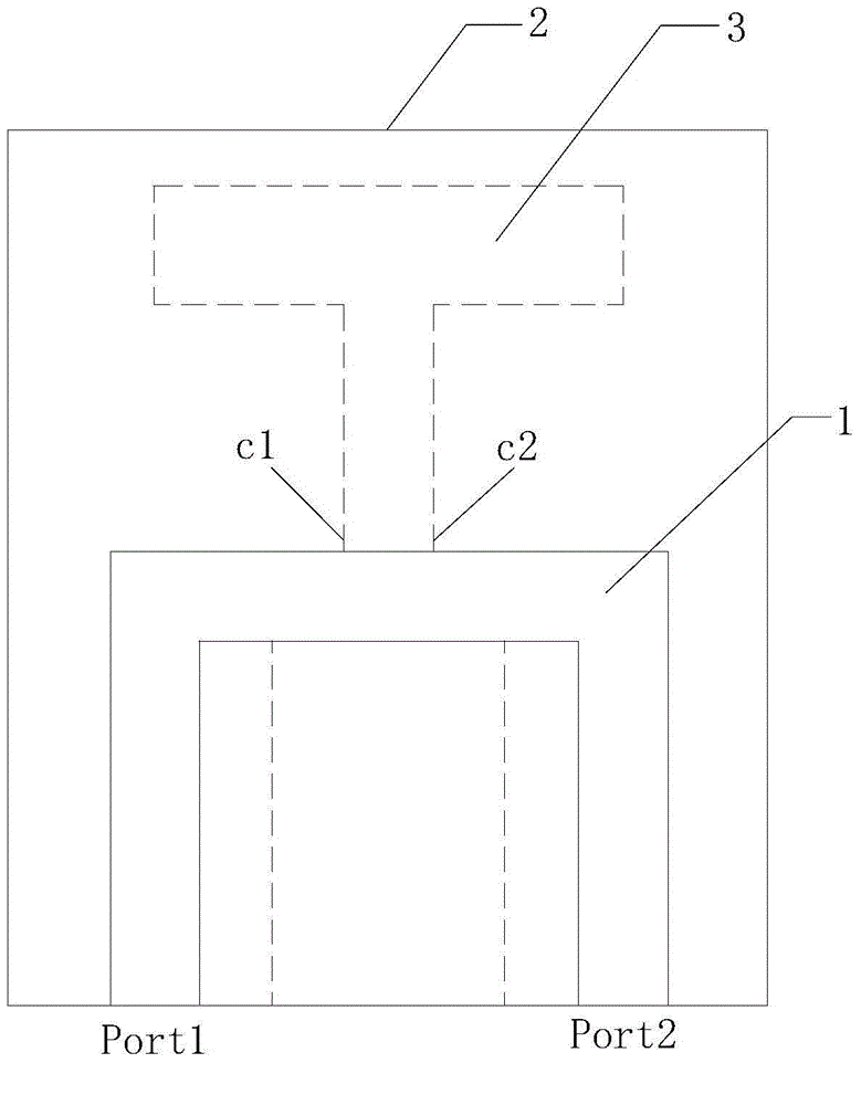
[0031] Such as figure 1 and figure 2 As shown, the antenna unit of this embodiment includes a floor and a microstrip feeder 1, the floor is arranged on the top layer of the dielectric substrate 2, and a T-shaped slot 3 is etched, and the microstrip feeder 1 is arranged on the bottom layer of the dielectric substrate 2;

[0032] The microstrip feeder 1 has a concave structure, and the two ends of the concave structure are respectively a first feeding port Port1 and a second feeding port Port2, and the first feeding port Port1 and the second feeding port Port2 are located at At the same edge of the bottom layer of the dielectric substrate, from figure 2 It can be seen from the figure that, unlike the traditional differential feed, the first feed port Port1 and the second feed port Port2 of the differential feed in this embodiment are directly connected, and the first feed port Port1 and the second feed port The electrical port Port2 feeds in differential signals with the sam...

Embodiment 2

[0035] Such as Figure 4 and Figure 5 As shown, the MIMO antenna of the present embodiment includes four antenna units (the antenna units of the above-mentioned embodiment 1) and a dielectric substrate 2, wherein the dielectric substrate 2 adopts an FR4 dielectric substrate with a dielectric constant of 4.4 and a thickness of 0.8mm; The three antenna units are the first antenna unit 4, the second antenna unit 5, the third antenna unit 6 and the fourth antenna unit 7. There are eight feeding ports in total. The floors of the four antenna units are connected and printed on the FR4 medium The top layer of the substrate; the microstrip feeder 1 of the four antenna units uses a 50Ω microstrip feeder and is printed on the bottom layer of the FR4 dielectric substrate, and uses the feed port to differentially feed the T-shaped slot 3 on the floor; the T of the four antenna units The rectangular slits 3 are arranged orthogonally to each other on the connected floor, and four rectangu...


PUM


Abstract

The invention discloses a difference slit MIMO (Multiple Input Multiple Output) antenna with a high common mode rejection ratio. The antenna comprises a medium substrate and multiple antenna units. Each antenna unit comprises a floor and a micro-strip feed line, wherein the floor is arranged on the top floor of the medium substrate and is etched with a T-shaped slit, and the micro-strip feed line is arranged on the bottom floor of the medium substrate and divides the T-shaped slit into an open-circuit slit and a short-circuit slit. The floors of the multiple antenna units are connected and cover the top floor of the medium substrate. According to the antenna provided by the invention, the specific difference feed structure and the slit combination are adopted to achieve a high common mode rejection effect. The antenna is advantaged by miniaturization, simple structure, high common mode rejection ratio, dual band, high isolation and the like, can meet requirements for miniaturization, low cost, easy processing, and easy integration of a difference circuit, and can be widely applied to a WLAN (Wireless Local Area Network) system.

Description

technical field [0001] The invention relates to a MIMO antenna, in particular to a differential slot MIMO antenna with a high common-mode rejection ratio, belonging to the field of wireless mobile communication. Background technique [0002] With the rapid development of wireless mobile communication in recent years, the resources for wireless mobile communication to increase the data transmission rate - frequency bandwidth and transmission power are on the verge of saturation. The rapid development of mobile communication has brought about the increasing shortage of spectrum resources. How to improve the transmission rate and quality of information on the existing spectrum resources has become the focus of research in today's society. MIMO (Multiple-Input Multiple-Output) wireless communication technology has entered people's field of vision because of its huge advantage of greatly increasing channel capacity and data transmission rate without losing frequency bandwidth and...

Claims


Application Information

Patent Timeline
Patent Type & Authority Applications(China)
IPC IPC(8): H01Q5/364H01Q5/20H01Q1/38
Inventor 柳炎炎涂治红褚庆昕
Owner SOUTH CHINA UNIV OF TECH
Why Eureka
Try Eureka