An automatic gas-liquid separation device and method for chlorine dioxide generator

A chlorine dioxide, gas-liquid separation technology, applied in separation methods, chemical instruments and methods, chlorine oxide and other directions, can solve problems such as failure to use normally, limit the promotion and application of chlorine dioxide, and inability to discharge residual liquid by itself. Easy to use effect

Active Publication Date: 2016-09-14
SHANDONG SHANDA WIT ENVIRONMENTAL ENGINEERING CO LTD
View PDF5 Cites 0 Cited by
  • Summary
  • Abstract
  • Description
  • Claims
  • Application Information

AI Technical Summary

Problems solved by technology

[0003] At present, there are many types of gas-liquid separation devices used in chlorine dioxide generators on the market, with different technologies and forms. However, these gas-liquid separators are only suitable for gas-liquid separation in low negative pressure environments, that is, in Chlorine dioxide generator under aeration conditions, negative pressure around -10kpa
It is not suitable for the high negative pressure sodium chlorate sulfuric acid chlorine dioxide generator without aeration, large output and high chlorine dioxide concentration. The negative pressure of this generator can reach above -30kpa, and the existing gas-liquid separation The device cannot be used normally in such a high negative pressure environment, and the residual liquid cannot be discharged by itself after separation, which largely limits the promotion and application of chlorine dioxide in the fields of bleaching and advanced oxidation

Method used


Image

  • An automatic gas-liquid separation device and method for chlorine dioxide generator
  • An automatic gas-liquid separation device and method for chlorine dioxide generator

Examples


Embodiment Construction

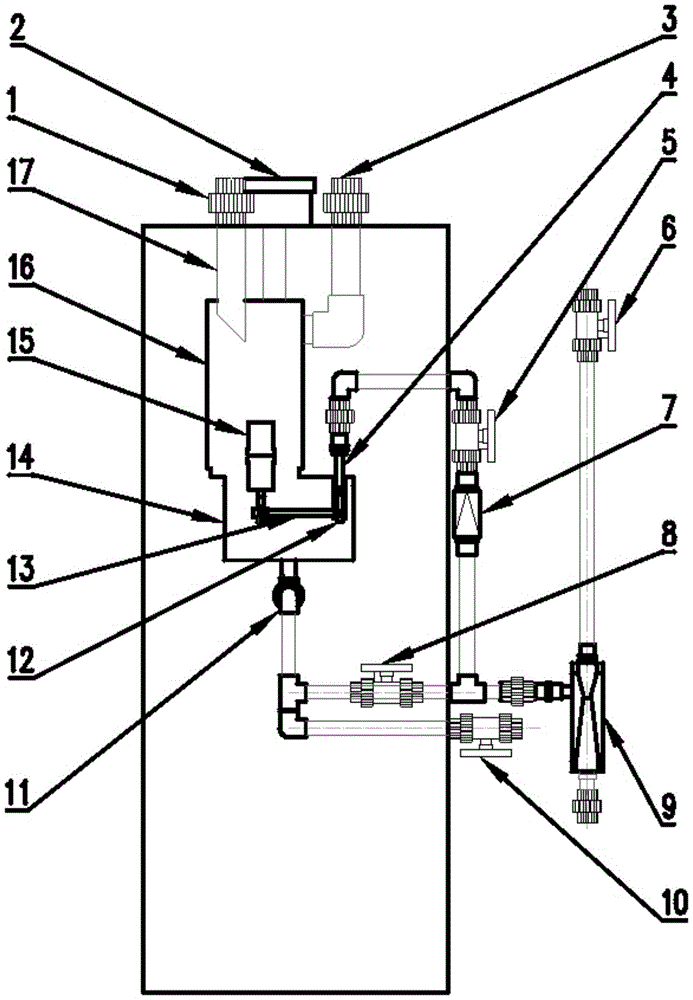
[0024] As shown in the figure, the present invention includes a casing, an automatic gas-liquid separation system and a residual liquid discharge system.

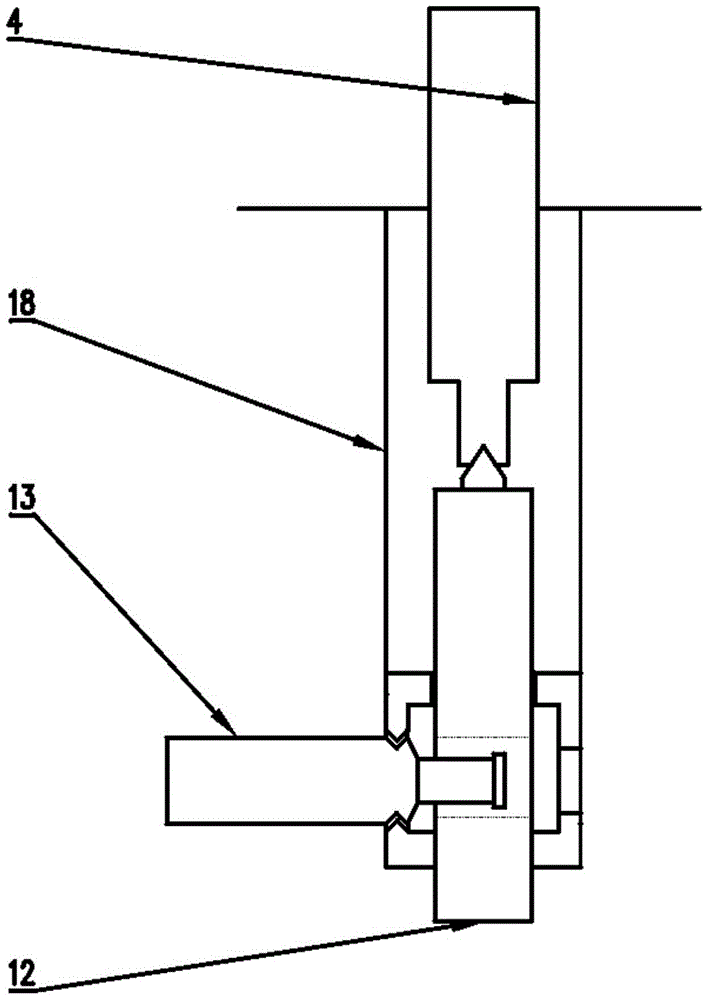
[0025] The gas-liquid automatic separation system includes a gas-liquid mixture inlet 1, an inner intubation tube 17, an air outlet 3, a separation box 16, a collecting tank 14, a float 15, a linkage rod 13, a sealing cone 12 and a liquid outlet pipe 4; The liquid mixture is connected to the inlet of the upper part of the separation box 16. The upper part of the separation box 16 is provided with an air outlet 3, the separation box 16 is connected to the liquid collecting tank 14, and the float 15 is connected to the outlet pipe 4 through the linkage rod 13 controlling the sealing cone 12, The fulcrum of the linkage rod 13 is fixed on the sealing support 18; the sealing support 18 is fixed on the top of the collecting tank 14, and the bottom of the collecting tank is provided with a sewage outlet 11 and a sewage valve 10.

[002...


PUM


Abstract

The invention discloses an automatic gas-liquid separation device and method for a chlorine dioxide generator under a high negative pressure environment. The device comprises a shell, an automatic gas-liquid separation system and a residual liquid exhaust system, wherein the automatic gas-liquid separation system comprises a gas-liquid mixture inlet, an internal insertion pipe, a gas outlet, a separation box, a liquid collection box, a floater, a linkage rod, a sealing cone and a liquid outlet pipe, and the residual exhaust system comprises a residual liquid valve, a check valve, a water jet and a power water valve; the gas-liquid mixture of chlorine dioxide generated by the generator, chlorine and a reaction liquid enters the separation tank through the mixture inlet and the internal insertion pipe; chlorine dioxide and chlorine are output through the gas outlet; the reaction liquid enters the liquid collection tank; the liquid level gradually rises; the floater floats to drive the sealing cone to leave the opening of the liquid outlet pipe; a solution enters the liquid outlet pipe and is discharged by virtue of negative pressure. According to the automatic gas-liquid separation device, gas-liquid separation can be automatically carried out so as to achieve the gas-liquid separation under high negative pressure environment; meanwhile, the difficulty that chlorine dioxide is limited by acidity when applied to the fields of bleaching and the like is solved.

Description

Technical field [0001] The invention relates to a device for automatic gas-liquid separation in a high negative pressure environment of a chlorine dioxide generator and a method for automatic gas-liquid separation using the device. Background technique [0002] The chlorine dioxide generator has a history of more than 20 years since its research and development. In the application, the negative pressure suction of the water ejector is generally used, and the chlorine dioxide gas and the residual liquid after the reaction are added to the treated water body for sterilization. For tap water, secondary water supply and other water bodies, the gas and liquid are added together, which will bring unreacted residues of raw materials into the water body, causing the disinfection by-product chlorate in the water body to exceed the standard; for application fields with special requirements, such as refined cotton, Papermaking bleaching and advanced oxidation of chemical raw materials requi...

Claims


Application Information

Patent Timeline
Patent Type & Authority Patents(China)
IPC IPC(8): B01D45/02C01B11/02
Inventor 张大钰董燕曲莹王明华冷俊龙历召龙范振奇
Owner SHANDONG SHANDA WIT ENVIRONMENTAL ENGINEERING CO LTD
Why Eureka
Try Eureka