A push button switch water distribution device

A water separation device and button technology, applied in the direction of spray device, spray device, etc., can solve the problem of inconvenient use and operation, and achieve the effects of convenient function switching, strong practicability and strong versatility

Active Publication Date: 2017-03-29
SINYU TECH FUJIAN
View PDF10 Cites 3 Cited by
  • Summary
  • Abstract
  • Description
  • Claims
  • Application Information

AI Technical Summary

Problems solved by technology

In some cases, it is inconvenient to use the operation

Method used


Image

  • A push button switch water distribution device
  • A push button switch water distribution device
  • A push button switch water distribution device

Examples


Embodiment Construction

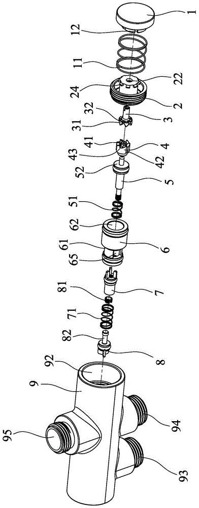
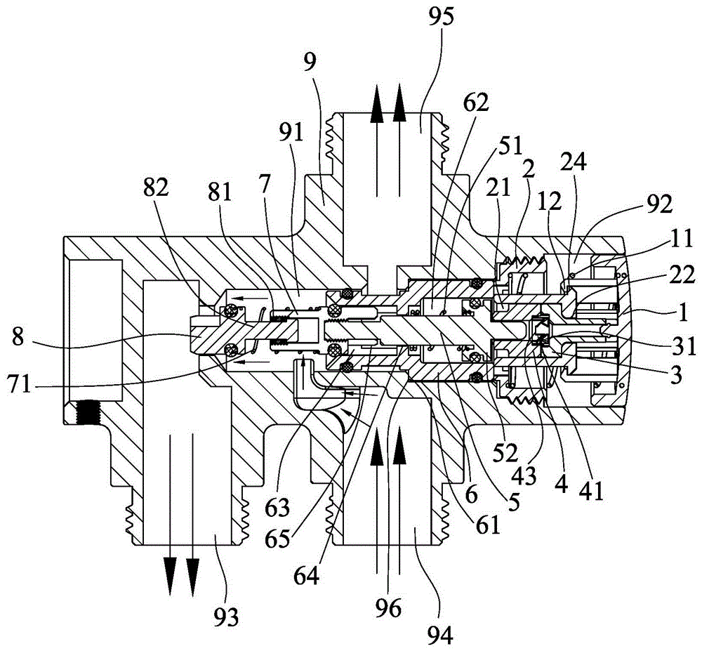
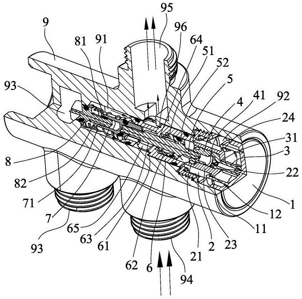
[0020] like Figure 1 to Figure 4 Shown is a preferred embodiment of the present invention.

[0021] A button switching water distribution device, including a button 1, a button spring 11, a locking seat 2, a pressing rod 3, a transmission member 4, a piston rod 5, a return spring 51, a fixing seat 6, a front plug 7, and a rear plug 8 and ontology 9.

[0022] The body 9 has an installation chamber 91, the front end of the installation chamber 91 is provided with an installation hole 92, the rear end of the installation chamber 91 is provided with a rear water outlet hole 93 (this embodiment is a lower outlet hole), and the side wall of the installation chamber 91 is provided with a side water inlet hole 94 (this embodiment is the lower water inlet hole) and the front water outlet hole 95 (this embodiment is the upper water outlet hole).

[0023] The locking seat 2 is fixed in the mounting hole 92 through screw fit. A front seat cavity 21 is formed in the locking seat 2, and...


PUM


Abstract

The invention discloses a button-switched water distributing device. According to the button-switched water distributing device, a locking seat is fixed into the mounting hole of a device body, and positioning ribs are formed inside the front cavity of the locking seat; a button is movably connected to the locking seat; a fixing seat is fixed into a mounting cavity of the device body and provided with a middle cavity, a rear cavity and a side holes; the front end of a pressure rod is fixed onto the button, the rear end of the pressure rod forms first bevel teeth inside the front cavity, and first tooth gaps are formed between every two neighboring first bevel teeth and matched with the positioning ribs; a transmission member is arranged inside the front cavity and the middle cavity, second bevel teeth are formed at the front end of the transmission member and matched with the first bevel teeth, and second tooth gaps or tooth slots are formed between every two neighboring second bevel teeth and matched with the positioning ribs; the piston head of a piston rod is arranged inside the middle cavity and connected with the transmission member; a reset spring is arranged between the piston head and the edge of a through hole; a front plug is fixedly connected at the rear end of the piston rod and movably connected with a rear plug in a sleeve mode, and a prestressed spring is arranged between the front plug and the rear plug. The button-switched water distributing device is simple in structure, convenient in function-switch and high in practicality.

Description

technical field [0001] The invention relates to a push-button switching water diversion device, which is suitable for all kitchen and bathroom products that need a diversion function, such as a shower device. Background technique [0002] Most of the water diversion devices of common showers realize the water diversion function by rotating the ceramic valve core. In some occasions, it is inconvenient to use and operate. Therefore, the present inventor has specially developed a water diversion device switched by a button, which realizes the water diversion function by pressing, making the switching operation easier and more convenient, and this case arises from this. Contents of the invention [0003] The object of the present invention is to provide a push-button switching water diversion device, which has a simple structure and is easy to use. [0004] In order to achieve the above object, the technical scheme of the present invention is as follows: [0005] A button s...

Claims


Application Information

Patent Timeline
Patent Type & Authority Patents(China)
IPC IPC(8): B05B1/16B05B1/18
CPCB05B1/1609B05B1/18B05B12/002
Inventor 余章军吴志峰
Owner SINYU TECH FUJIAN
Why Eureka
Try Eureka