Supercharge Your Innovation With Domain-Expert AI Agents!

Wireless power transmission device, supply power control method for wireless power transmission device, and method for manufacturing wireless power transmission device

A technology of wireless power transmission and power control, which is applied to circuit devices, battery circuit devices, transportation and packaging, etc., and can solve the problem of increasing the number of parts

Inactive Publication Date: 2015-10-21
NITTO DENKO CORP
View PDF8 Cites 0 Cited by
  • Summary
  • Abstract
  • Description
  • Claims
  • Application Information

AI Technical Summary

Problems solved by technology

[0007] However, providing an impedance matching device separately is disadvantageous in that the number of parts increases for portable electronic devices that require portability, miniaturization, and cost reduction

Method used


Image

  • Wireless power transmission device, supply power control method for wireless power transmission device, and method for manufacturing wireless power transmission device
  • Wireless power transmission device, supply power control method for wireless power transmission device, and method for manufacturing wireless power transmission device
  • Wireless power transmission device, supply power control method for wireless power transmission device, and method for manufacturing wireless power transmission device

Examples


Embodiment approach

[0058] First, before describing the power supply control method of the wireless power transmission device and the manufacturing method of the wireless power transmission device, the wireless power transmission device 1 designed and manufactured by the power supply control method or the manufacturing method will be described.

[0059] (Structure of wireless power transmission device 1)

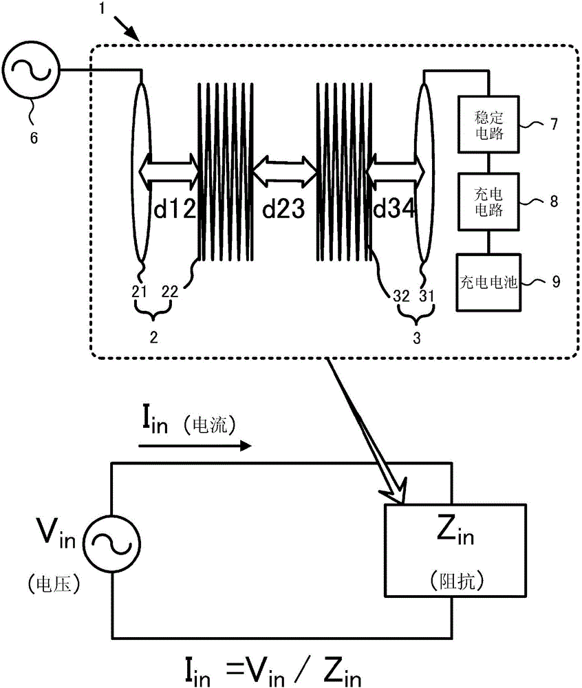
[0060] Such as figure 1 As shown, the wireless power transmission device 1 includes a power supply module 2 including a power supply coil 21 and a power supply resonator 22 , and a power receiving module 3 including a power receiving coil 31 and a power receiving resonator 32 . Furthermore, an AC power source 6 having an oscillation circuit for setting the drive frequency of the electric power supplied to the power supply module 2 to a predetermined value is connected to the power supply coil 21 of the power supply module 2 , and is connected to the power reception coil 31 of the power receptio...

other Embodiment approach

[0183] In the description of the above-mentioned manufacturing method, the wireless headphone 200 was exemplified and described, but as long as it is a device equipped with a rechargeable battery, it can also be used in a tablet PC, a digital camera, a mobile phone, and an earphone-type music player. , hearing aids, sound collectors, etc.

[0184] In addition, in the above description, the wireless power transmission device 1 that performs power transmission by utilizing the resonance phenomenon (magnetic field resonance state) between the resonators (coils) of the power supply module 2 and the power reception module 3 to couple the magnetic field is exemplified. For the sake of explanation, it can also be applied to the wireless power transmission device 1 that performs power transmission using electromagnetic induction between coils.


PUM

PropertyMeasurementUnit
diameteraaaaaaaaaa

Abstract

A wireless power transmission device (1) supplies power from a power supplying module (2) equipped with a power supplying coil (21) and a power supplying resonator (22) to a power receiving module (3) equipped with a power receiving coil (31) and a power receiving resonator (32) by changing magnetic field. In a supply power control method for the wireless power transmission device (1), the power is supplied with such a value that the driving frequency of the power supplied to the power supplying module (2) does not become the resonance frequencies of the power supplying module (2) and the power receiving module (3). The element values of circuit elements constituting the power supplying module (2) and the power receiving module (3) are used as parameters, and by changing each of the parameters, the input impedance (Zin) of the wireless power transmission device (1) is set to adjust the power to be supplied.

Description

technical field [0001] The present invention relates to a wireless power transmission device capable of improving design freedom, a power supply control method of the wireless power transmission device, and a manufacturing method of the wireless power transmission device. Background technique [0002] In recent years, portable electronic devices such as notebook PCs, tablet PCs, digital cameras, mobile phones, portable game consoles, earphone music players, wireless headsets, hearing aids, recorders, etc. universal. Furthermore, most of these portable electronic devices are equipped with rechargeable batteries, and need to be charged periodically. In order to simplify the charging operation of the rechargeable battery of the electronic device, the power supply technology (wireless power transmission technology that changes the magnetic field and transmits power) is used between the power supply device and the power receiving device mounted on the electronic device. Devices...

Claims


Application Information

Patent Timeline
Patent Type & Authority Applications(China)
IPC IPC(8): H02J17/00H01F38/14H02J7/00
CPCH02J7/025H02J5/00H02J50/10H02J7/00304H02J7/00302H02J50/12
Inventor 畑中武蔵津田尚
Owner NITTO DENKO CORP
Features
  • R&D
  • Intellectual Property
  • Life Sciences
  • Materials
  • Tech Scout
  • Unparalleled Data Quality
  • Higher Quality Content
  • 60% Fewer Hallucinations
Learn More