Discharge device adjustable centrifugal machine

An unloading device and adjustable technology, which is applied in the field of centrifuges, can solve the problems of large chip resistance of wide scrapers, uneven force on the tool, and small chip resistance, etc., so as to increase the service life, improve the service life and high discharge efficiency Effect

Active Publication Date: 2015-10-28
湖南捷瑞化工有限公司
View PDF6 Cites 2 Cited by
  • Summary
  • Abstract
  • Description
  • Claims
  • Application Information

AI Technical Summary

Problems solved by technology

[0002] Existing vertical centrifuges mostly use a scraper to unload the filter cake. If a wide scraper is used to unload the filter cake, it will be carried out along the entire height of the drum, and the unloading is rapid. However, the wide scraper has a large chip resistance, so it is mostly suitable for For loose filter cakes and low drum heights, use a narrow scraper to unload chips with little resistance, and can be used for unloading filter cakes with different hardness or a little viscosity. When unloading with a narrow scraper, the solid phase at the edge cannot be pulled smoothly. In the process of centrifugal dehydration of the material, the solid phase forms a gradually thicker filter cake from top to bottom along the drum under the action of gravity and centrifugal force. Since the angle of the cutter is not adjustable, the scraping During the filter cake process, the force on the bottom of the cutter is relatively large, the force on the cutter is uneven, and the cutter is easy to be damaged

Method used


Image

  • Discharge device adjustable centrifugal machine
  • Discharge device adjustable centrifugal machine
  • Discharge device adjustable centrifugal machine

Examples


Embodiment Construction

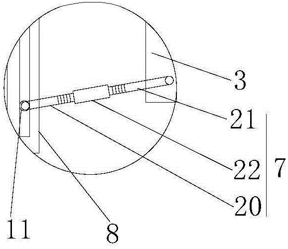
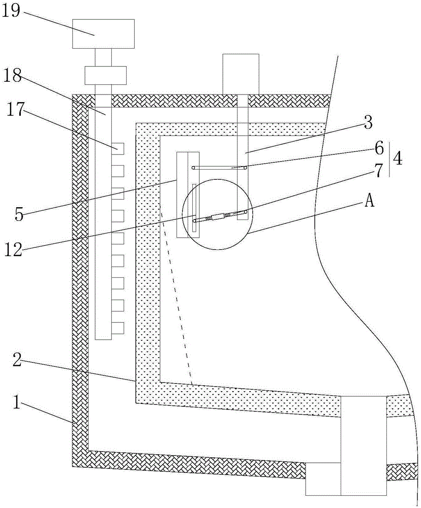
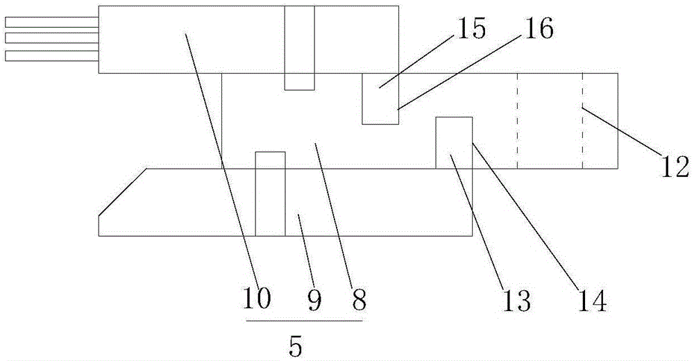
[0018] Such as figure 1 , figure 2 , image 3 as shown, figure 1 It is a structural schematic diagram of an adjustable centrifuge with an unloading device proposed by the present invention; figure 2 It is a structural schematic diagram of a scraper assembly in a centrifuge with an adjustable unloading device proposed by the present invention; image 3 It is an enlarged view of part A of a centrifuge with an adjustable unloading device proposed by the present invention.

[0019] refer to figure 1 , a centrifuge with an adjustable unloading device proposed by the present invention includes a casing 1, a drum 2, an inner unloading device and an outer unloading device, the drum 2 is rotatably installed in the casing 1, and the first The driving device drives the rotation;

[0020] The inner unloading device includes a second driving device, a driving rod 3, a connecting assembly 4 and a cutter assembly 5. The driving rod 3 extends into the drum 2 from above, and the second...


PUM


Abstract

The invention provides a discharge device adjustable centrifugal machine which comprises a chassis, a rotating drum, an inner discharge device and an outer discharge device, wherein the rotating drum is rotationally mounted in the chassis and is driven to rotate by a first driving device; the inner discharge device comprises a second driving device, a driving rod, a connecting assembly and a cutter assembly; the driving rod stretches into the rotating drum from the upside; the second driving device drives the driving rod to move up and down; the outer discharge device comprises a vent pipe stretching into a part between the chassis and the rotating drum; a plurality of nozzles are formed on the vent pipe; the vent pipe is communicated with a blower; the nozzles face towards the rotating drum; the cutter assembly comprises a cutter rest, a cutter and a hair brush; and the cutter and the hair brush are respectively arranged on the two sides of the cutter rest. The discharge device adjustable centrifugal machine discharges more easily and cleanly, and the service life is increased.

Description

technical field [0001] The invention relates to the technical field of centrifuges, in particular to a centrifuge with an adjustable discharge device. Background technique [0002] Existing vertical centrifuges mostly use a scraper to unload the filter cake. If a wide scraper is used to unload the filter cake, it will be carried out along the entire height of the drum, and the unloading is rapid. However, the wide scraper has a large chip resistance, so it is mostly suitable for For loose filter cakes and low drum heights, use a narrow scraper to unload chips with little resistance, and can be used for unloading filter cakes with different hardness or a little viscosity. When unloading with a narrow scraper, the solid phase at the edge cannot be pulled smoothly. In the process of centrifugal dehydration of the material, the solid phase forms a gradually thicker filter cake from top to bottom along the drum under the action of gravity and centrifugal force. Since the angle of...

Claims


Application Information

Patent Timeline
Patent Type & Authority Applications(China)
IPC IPC(8): B04B11/08B04B15/06
Inventor 崔李黄艳
Owner 湖南捷瑞化工有限公司
Why Eureka
Try Eureka