Telescopic Rebar Splice Kit

A telescopic and kit technology, applied in the direction of building components, building reinforcements, structural elements, etc., can solve problems such as unusable connection structures

Active Publication Date: 2017-11-17
裴敏雅
View PDF6 Cites 0 Cited by
  • Summary
  • Abstract
  • Description
  • Claims
  • Application Information

AI Technical Summary

Problems solved by technology

This technology is only applicable to a specific state, that is, two steel bars are on a straight line. If the two steel bars are in parallel misalignment or have a certain angle, the connection structure cannot be used.

Method used


Image

  • Telescopic Rebar Splice Kit
  • Telescopic Rebar Splice Kit
  • Telescopic Rebar Splice Kit

Examples


Embodiment Construction

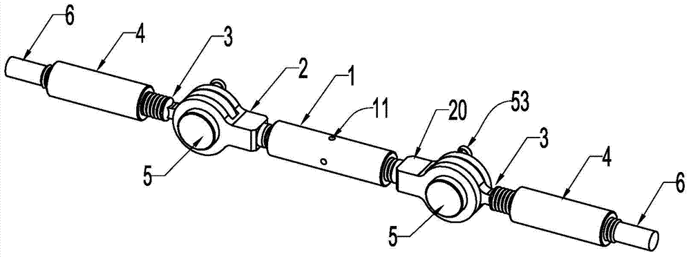
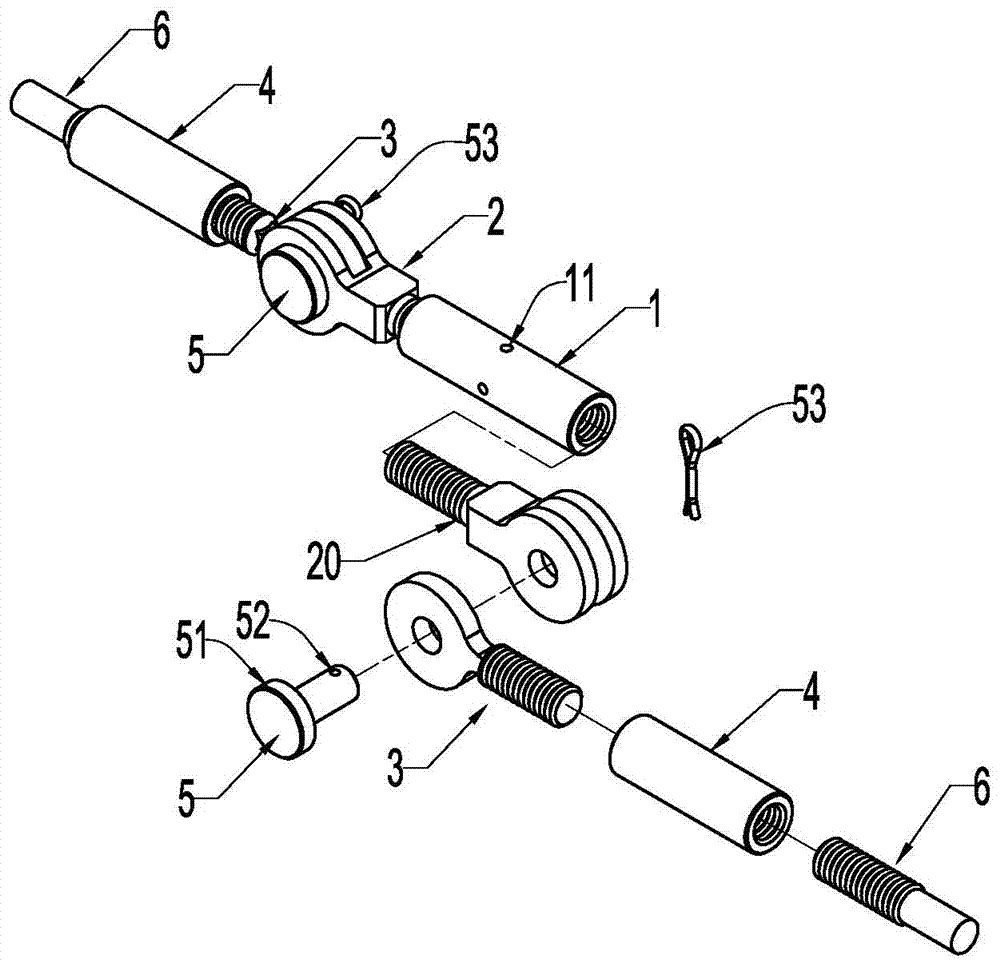
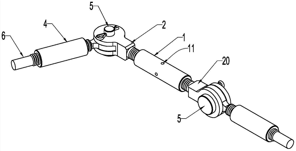
[0024] refer to figure 1 , figure 2 and image 3 , a telescopic steel bar connection kit, the main body of the kit includes a two-way screw sleeve 1, a forward screw seat 2, a reverse screw seat 20, a screw joint 3, a one-way screw sleeve 4 and a pin shaft 5; one end of the two-way screw sleeve 1 The inner thread of the thread is the same as the inner thread of the one-way thread sleeve 4, the thread of the forward screw seat 2, the screw joint 3 and the outer thread of the steel bar head 6 are the same, and the outer thread of the steel bar head 6 is rough-turned on-site All parts with the same thread teeth can be combined flexibly, and the ultimate goal is to use the main body of the kit to connect the two steel bar heads 6 to replace traditional welding and other processes. The combination of the main body of the kit has the following four typical connection structures:

[0025] One of the basic types:

[0026] The forward-rotating screw seat 2 and the reverse-rotating...


PUM


Abstract

The invention relates to a telescopic steel bar connection kit, the main body of which includes a two-way screw sleeve, a forward screw seat, a reverse screw seat, a screw joint, a one-way screw sleeve and a pin shaft; one end of the two-way screw sleeve The inner thread of the thread is consistent with the inner thread of the one-way thread sleeve, and the outer thread of the forward screw seat, screw joint and steel head pier is consistent; each part in the kit can be organically combined, such as adding or subtracting Parts, for the butt connection of two steel bar heads with different spacing, and provide a kit for the connection of steel bar heads at the construction site. The combination method is flexible. According to the requirements of the steel bar spacing, it can reduce the number of parts to form a short-distance connection, and can also increase the number of parts in series to meet the needs of long-distance connections. With the help of two-way threaded sleeves, it can achieve tension and eliminate connection gaps; the connection is reliable, no The amount of deformation can meet the stress design requirements, and it is suitable for the connection of two steel bar heads with dislocation and different angles, which greatly facilitates the construction of steel bar connection.

Description

Technical field: [0001] The invention belongs to the field of building construction, in particular to a telescopic steel bar connection kit. Background technique: [0002] With the promotion of construction industrialization, pilot projects are being carried out all over the country, and the most difficult problem to solve is the structural earthquake resistance and waterproofing. The solution given by the experts is that beam-column joints, beam ends and beam ends, between plate ends and plate ends, between plates and beam-columns are cast-in-place, and beam-slab surfaces are laminated and cast-in-place. But the difficulty lies in the butt joint of the force-transmitting steel bars between the concrete prefabricated components. If the welding scheme is used, the welding quality is difficult to meet the requirements due to the extremely limited operating space, and it is labor-intensive and time-consuming; if the scheme of excessive reinforcement plus traditional spiral pip...

Claims


Application Information

Patent Timeline
Patent Type & Authority Patents(China)
IPC IPC(8): E04C5/16E04C5/18
Inventor 裴敏雅
Owner 裴敏雅
Why Eureka
Try Eureka