Millimeter wave high-resolution imaging medium lens antenna design method

A high-resolution, lens-antenna technology, applied to antennas, electrical components, etc., can solve the problem that the definition of optical system resolution cannot be applied to millimeter-wave imaging systems, the design of millimeter-wave imaging lens antennas has no guiding significance, and the lack of millimeter-wave antennas, etc. , to achieve the effect of clear thinking and simple operation

Active Publication Date: 2016-01-27
UNIV OF ELECTRONICS SCI & TECH OF CHINA
View PDF1 Cites 6 Cited by
  • Summary
  • Abstract
  • Description
  • Claims
  • Application Information

AI Technical Summary

Problems solved by technology

Because the working principle of the millimeter-wave antenna and the photosensitive film are fundamentally different, the resolution definition of the optical system cannot be applied to the millimeter-wave imaging system, and the definition of the resolution of the optical system has no guiding significance for the design of the millimeter-wave imaging lens antenna
Researchers in the United States, Japan and other countries have studied and designed millimeter-wave lens antennas, but they are all based on the principle of designing optical imaging systems, lacking the support of millimeter-wave antenna theory

Method used


Image

  • Millimeter wave high-resolution imaging medium lens antenna design method
  • Millimeter wave high-resolution imaging medium lens antenna design method
  • Millimeter wave high-resolution imaging medium lens antenna design method

Examples


Embodiment Construction

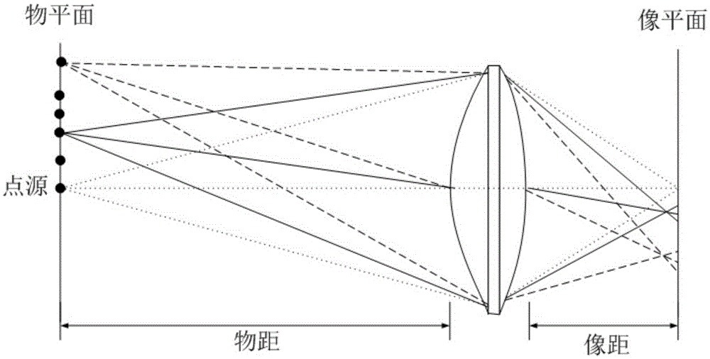
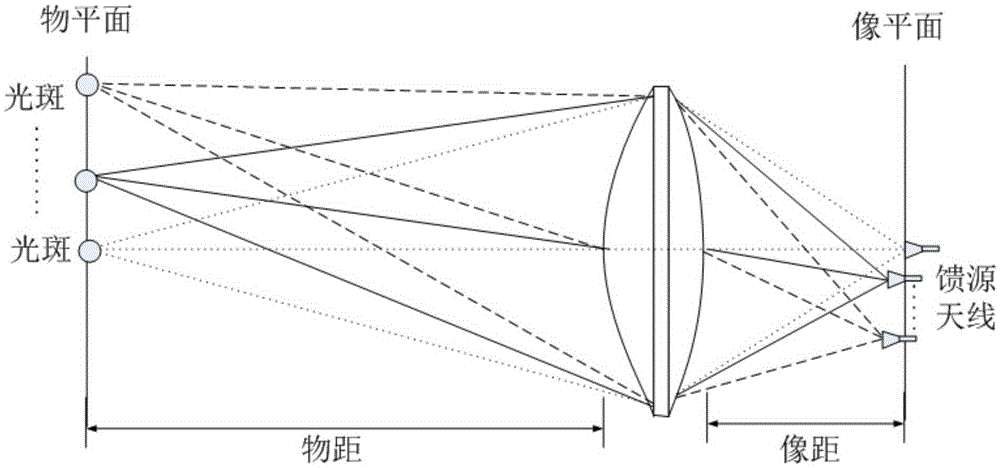
[0014] Below in conjunction with accompanying drawing and specific embodiment, the present invention is further described: design a millimeter-wave imaging dielectric lens antenna, require the lens antenna working object distance to be greater than 3m, can distinguish the object that size is d<30mm on the object plane or distance is d< 30mm for two objects. According to this index requirement, a design method of millimeter-wave high-resolution imaging dielectric lens antenna is given below.

[0015] The main work of designing the lens antenna is the selection and optimization of the lens surface equation, and the arrangement of the feed antenna array. The object distance of the lens antenna system is So, the image distance is Si, the dielectric constant of the lens material is ε, and the lens diameter is D.

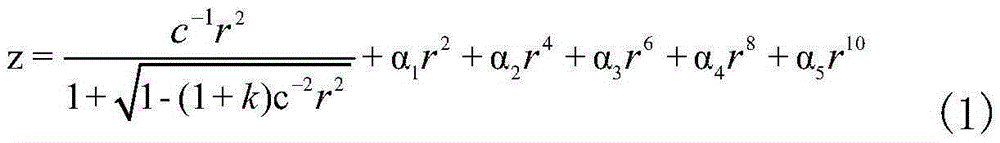
[0016] A biconvex lens is selected as the lens form, and the curved surfaces on both sides are even-order aspheric surfaces. The surface equation can be expressed as

...


PUM


Abstract

The invention discloses a millimeter wave high-resolution imaging medium lens antenna design method. The method is a design method combining optical lens design technology and millimeter wave antenna design theory, relating to the technical field of a millimeter wave antenna. By using an optical lens curved surface, the wave aberration and the geometrical aberration of a system are optimized by an optical design method, so that -3dB light spot diameter of feed source antenna units on an object plane is the smallest, and the gain inequality value of each feed source antenna unit is smaller than 1dB. The design method has the characteristics of simpleness and easy use, and the resolution ratio of the millimeter wave lens antenna is innovatively defined. The design method provided can be applied to a millimeter wave imaging system.

Description

technical field [0001] The invention belongs to the technical field of millimeter-wave imaging antennas, and in particular relates to a design method of a millimeter-wave high-resolution imaging medium lens antenna for a millimeter-wave imaging system. Background technique [0002] The principle of millimeter-wave imaging is similar to that of optical imaging, except that the optical imaging system uses photosensitive film or CCD on the focal plane of the lens, and the working frequency band is visible light or infrared light, while the millimeter-wave imaging system uses a millimeter-wave antenna array. The frequency band is the millimeter wave frequency band. The optical imaging system has a high resolution, but it is difficult to work in rainy, foggy and dusty weather, and it cannot image objects under obstacles such as mud or clothing. Compared with visible light and infrared light, millimeter wave has stronger penetrating ability and can penetrate opaque objects such a...

Claims


Application Information

Patent Timeline
Patent Type & Authority Applications(China)
IPC IPC(8): H01Q19/06
Inventor 陈其科周景石孙震朱贵德李道通张永鸿林先其樊勇
Owner UNIV OF ELECTRONICS SCI & TECH OF CHINA
Why Eureka
Try Eureka