Automatic focusing device and method

An auto-focus and focus position technology, applied in the field of imaging, can solve the problems that affect the imaging performance of camera equipment, the focus performance cannot be achieved well, and the focus effect cannot be obtained, so as to achieve the accuracy of focus and improve the focus speed and accuracy , the effect of good focusing results

Active Publication Date: 2016-03-30
BEIJING SPREADTRUM HI TECH COMM TECH CO LTD
View PDF6 Cites 6 Cited by
  • Summary
  • Abstract
  • Description
  • Claims
  • Application Information

AI Technical Summary

Problems solved by technology

[0015] It is impossible to focus well on subjects with thin lines and only weak textures, which may easily cause focus errors and take too long; in low-contrast and low-light conditions, the focus performance cannot be achieved well; Objects, polarized subjects, black subjects, or subjects with a mirror surface cannot be accurately focused
[0016] The focusing system and focusing method of the prior art cannot obtain a better focusing effect, thus affecting the imaging performance of the camera equipment

Method used


Image

  • Automatic focusing device and method
  • Automatic focusing device and method
  • Automatic focusing device and method

Examples


Embodiment 1

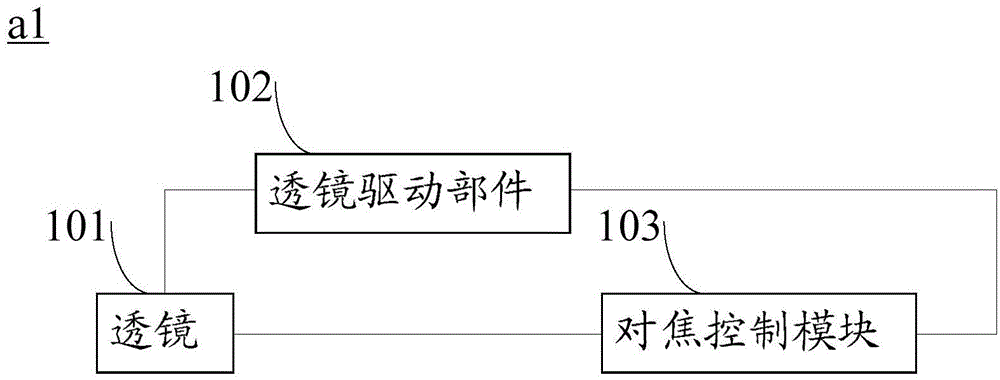
[0065] Such as image 3 The shown autofocus device a1 is suitable for an imaging device (similar in structure to the imaging device 1 ), and includes: a lens 101 , a lens driving component 102 and a focusing control module 103 .

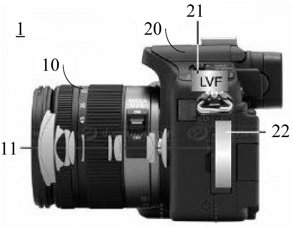
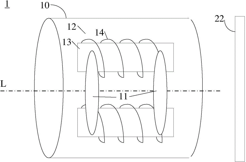
[0066] The lens 101 is provided in the lens system 10 and generally refers to a plurality of lenses on the same optical axis L of the imaging device 1 . The lens 101 includes a lens for automatic focus control, also called a focus lens. The focusing lens can move back and forth along the optical axis of the lens, and is driven by the response of the lens driving part 102 to the signal related to the focusing result (that is, the focusing signal), thereby moving the focusing lens and changing the lens position, and the lens position can be changed by The lens position detection part inside or outside the auto-focus device detects, which is beneficial to the re-driving of the subsequent focus lens. The original image can be generated based on the ligh...

Embodiment 2

[0114] Such as Figure 7 In the shown autofocus device a2, different from the first embodiment, the focus control module 103' further includes: a statistical unit; the statistical unit is adapted to output the frequency response according to the frequency response value of the image data of the pixel of interest result.

[0115] The output of the statistical unit is the one-to-one correspondence between the frequency response value of the pixel of interest on the original image and its corresponding frequency response result, and the corresponding relationship can be mapped under different functions, such as those involved in the first embodiment sum or average of .

[0116] For one focusing process, the output frequency response result of the statistical unit may be output in the form of the focusing statistical curve described in the first embodiment.

Embodiment 3

[0118] Such as Figure 8 The shown autofocus device a3 is different from the first embodiment, and further includes: a focus position search module 104 .

[0119] The focus position search module 104 is adapted to continuously obtain the frequency response result output by the focus control module 103 during the process of driving the focus lens by the lens driving component 102, search for the corresponding relationship between the lens position and the frequency response result, and based on the obtained The corresponding relationship identifies the expected frequency response result.

[0120] Corresponding to the focus statistical curve in Embodiment 1, the process of identifying the expected frequency response result by the focus position search module 104 is the process of obtaining the global maximum value of the focus statistical curve, outputting the focus position corresponding to the global maximum value, and then sending a corresponding The signal is sent to the le...


PUM


Abstract

The invention relates to an automatic focusing device and method. The automatic focusing device comprises a lens, a lens driving part and a focusing control module. An initial image can be generated based on light guiding of the lens to a shot body. The focusing control module is used for obtaining a frequency response result of interested pixel points in the initial image. The lens driving part is used for driving the lens so as to obtain the expected frequency response result and using the position of the lens as a focusing position for driving the lens when the expected frequency response result is achieved. According to the invention, the focusing accuracy and the focusing speed of the shot body under the conditions of low-contrast weak textures and weak light are improved.

Description

technical field [0001] The invention relates to the field of imaging, in particular to an automatic focusing device and an automatic focusing method. Background technique [0002] Camera devices, such as cameras and mobile phones with integrated cameras, are usually capable of autofocus. [0003] Autofocus (AutoFocus) utilizes the principle of light reflection of the subject. The light reflected by the subject is accepted by the image sensor (such as CCD / CMOS sensor) of the camera and other imaging equipment, and processed by the computer to drive the electric focusing device to focus. [0004] A complete autofocus device may include: at least one imaging lens, at least one focus lens, a photosensitive device, and a focus adjustment mechanism. [0005] In terms of basic principles, autofocus methods can be divided into two categories: one is based on the distance measurement between the lens and the object to be photographed, and the other is based on the focus detection au...

Claims


Application Information

Patent Timeline
Patent Type & Authority Applications(China)
IPC IPC(8): G03B13/36H04N5/232G03B30/00
CPCH04N23/67
Inventor 胡毅王浩王微
Owner BEIJING SPREADTRUM HI TECH COMM TECH CO LTD
Why Eureka
Try Eureka