Focus motor, closed-loop control method of focus motor, and camera equipment

A mover and plate technology, applied in the field of photography, can solve the problems of occupying a large internal space, a large space for the motor, which is not conducive to reducing the cost of the focusing motor, and achieve the effect of improving accuracy and avoiding the influence of capacitive signals

Active Publication Date: 2022-04-12
CHIPSEMI SEMICON (NINGBO) CO LTD
View PDF0 Cites 0 Cited by
  • Summary
  • Abstract
  • Description
  • Claims
  • Application Information

AI Technical Summary

Problems solved by technology

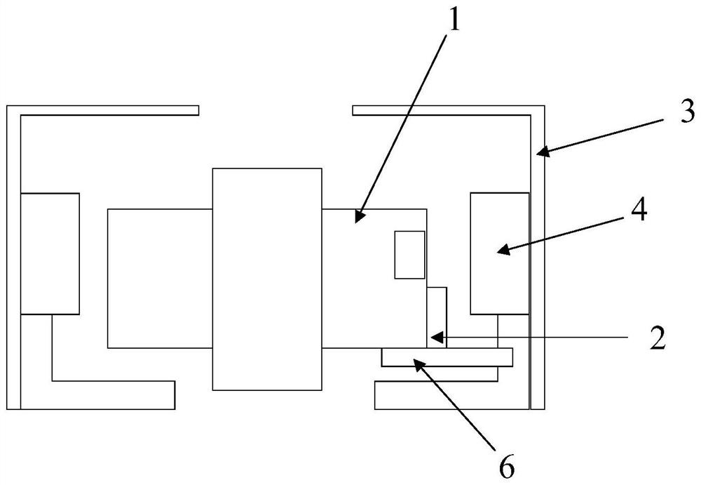
[0003] The inventors found that there are at least the following problems in the related technologies of closed-loop control to achieve focusing: In the related technologies, Hall sensors are usually used to detect the real-time position of the mover, and the mover is detected by the Hall sensor and the corresponding magnet for sensing. However, setting Hall sensors and sensing magnets inside the motor will occupy a large internal space, which is not conducive to realizing the miniaturization of the motor
In addition, since the Hall sensor and the sensing magnet occupy a large space inside the motor, the volume of the magnets and coils used to drive the mover is limited under the premise that the internal space of the motor is limited, which is not conducive to improving the performance of the motor. The driving force of the motor reduces the focusing efficiency of the focusing motor
Finally, the cost of the Hall sensor is relatively high, which is not conducive to reducing the cost of the focus motor

Method used


Image

  • Focus motor, closed-loop control method of focus motor, and camera equipment
  • Focus motor, closed-loop control method of focus motor, and camera equipment
  • Focus motor, closed-loop control method of focus motor, and camera equipment

Examples


Embodiment Construction

[0028] In order to make the purpose, technical solutions and advantages of the embodiments of the present invention clearer, the embodiments of the present invention will be described in detail below with reference to the accompanying drawings. However, those skilled in the art can understand that in each embodiment of the present invention, many technical details are provided for readers to better understand the present application. However, even without these technical details and various changes and modifications based on the following embodiments, the technical solutions claimed in this application can also be realized.

[0029] The division of the following embodiments is for the convenience of description, and should not constitute any limitation to the specific implementation of the present invention, and the various embodiments can be combined and referred to each other on the premise of no contradiction.

[0030] The first embodiment of the present invention relates t...


PUM


Abstract

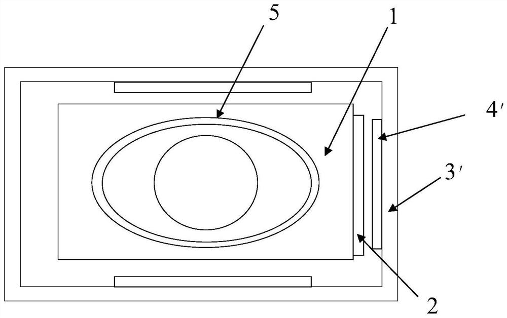
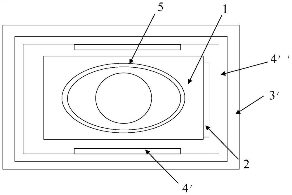
The embodiment of the present invention relates to the technical field of imaging, and discloses a focus motor, a closed-loop control method for the focus motor, and an imaging device. In the present invention, the focus motor includes: a mover, a pole plate arranged on the mover, a stator, a conductive part arranged on the stator, and a processing unit, the pole plate and the conductive part are arranged oppositely, and the front of the pole plate and the conductive part As the area changes with the movement of the mover, the processing unit is connected to the polar plate and the conductive component, and the processing unit controls the mover to move in the focusing direction according to the capacitance signal of the capacitance formed by the polar plate and the conductive component. Thus, the closed-loop control of the focus motor is realized, the cost of the motor is reduced, and the internal volume of the motor is saved.

Description

technical field [0001] Embodiments of the present invention relate to the technical field of imaging, and in particular to a focus motor, a closed-loop control method for the focus motor, and an imaging device. Background technique [0002] With the development of camera technology, in order to achieve fast and stable focusing, the camera modules in most current camera equipment usually adopt a closed-loop control method to detect the real-time position of the mover in the focus motor during the focusing process, and according to the detected The position of the mover adjusts the driving current of the drive lens, so that the mover can quickly reach the accurate focus position. [0003] The inventors found that there are at least the following problems in the related technologies of closed-loop control to achieve focusing: In related technologies, Hall sensors are usually used to detect the real-time position of the mover, and the mover is detected by the Hall sensor and the...

Claims


Application Information

Patent Timeline
Patent Type & Authority Patents(China)
IPC IPC(8): H02K11/21H02K11/028G02B7/04G02B7/08G03B13/34
CPCH02K11/21H02K11/028G02B7/04G02B7/08G03B13/34
Inventor 张耀国夏波
Owner CHIPSEMI SEMICON (NINGBO) CO LTD
Why Eureka
Try Eureka