
Ocular inlay with locator

Inactive Publication Date: 2006-10-19
ACUFOCUS
View PDF77 Cites 221 Cited by
  • Summary
  • Abstract
  • Description
  • Claims
  • Application Information

AI Technical Summary

Benefits of technology

[0009] There is a need for a system and device to provide reliable access to an implanted ocular device post-implantation to facilitate removal of the device. There is a need for a system and device to accurately locate the level or depth within an ocular structure where an implanted device is located without undue trauma to the patient. The system and device should avoid making incisions in the pupil region, which is a region within a boundary coincident with the largest pupil size under the normal range of conditions. It would also be advantageous for the system or device for locating an implantable ocular device not be visible to or otherwise be unobtrusive to the patient and to others interacting with the patient.

Problems solved by technology

Many people suffer one or more vision defects that impair accommodation.
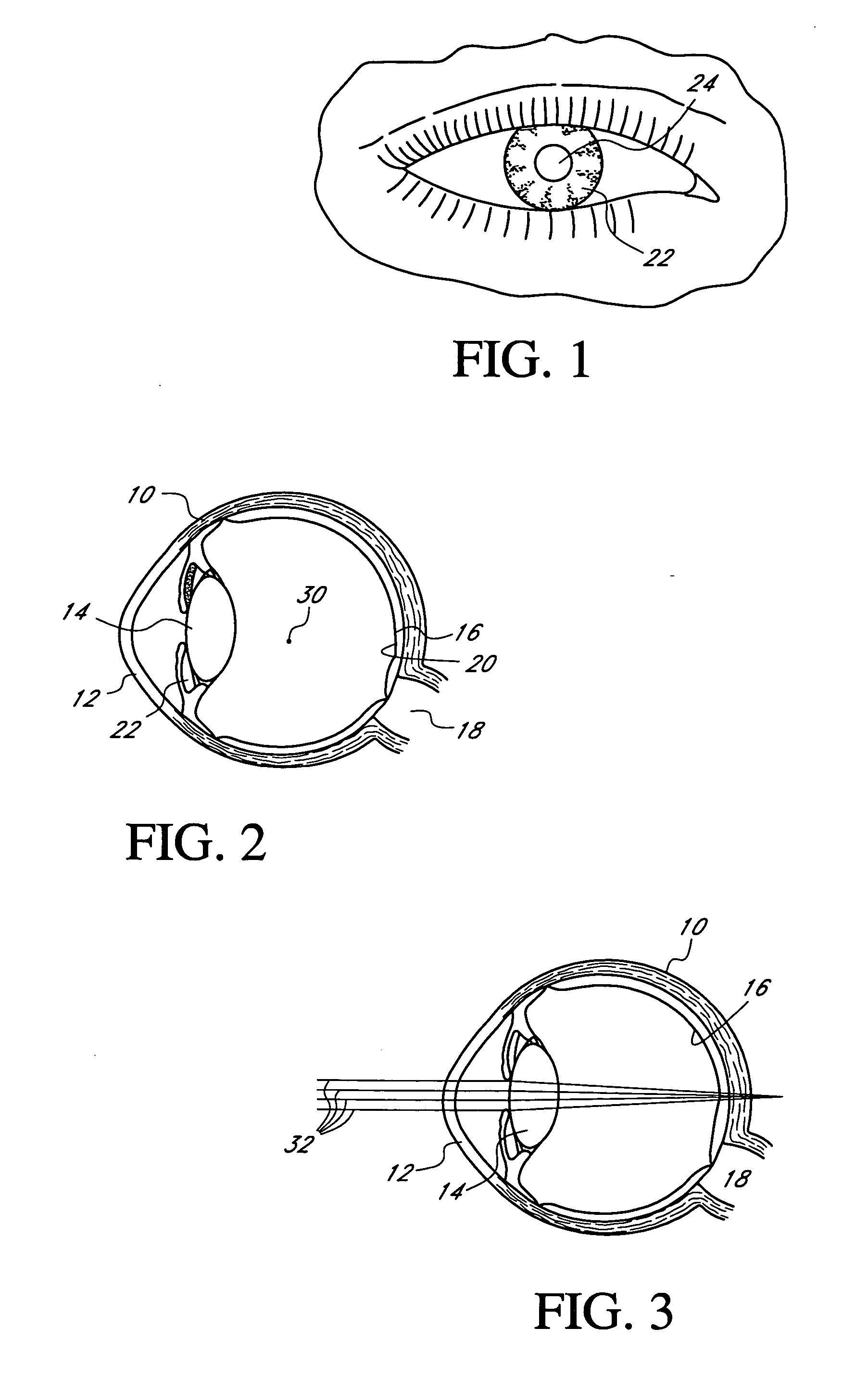
For example, presbyopia is a fairly common condition in people over age 40 that compromises the ability to accommodate for near objects.
If a relatively thin ocular device is implanted within the cornea, locating the device during removal can be difficult.
Thus, it can prove difficult to successfully access an ocular device implanted in the cornea without further harming the patient's vision.

Method used


Image

  • Ocular inlay with locator
  • Ocular inlay with locator
  • Ocular inlay with locator

Examples


Embodiment Construction

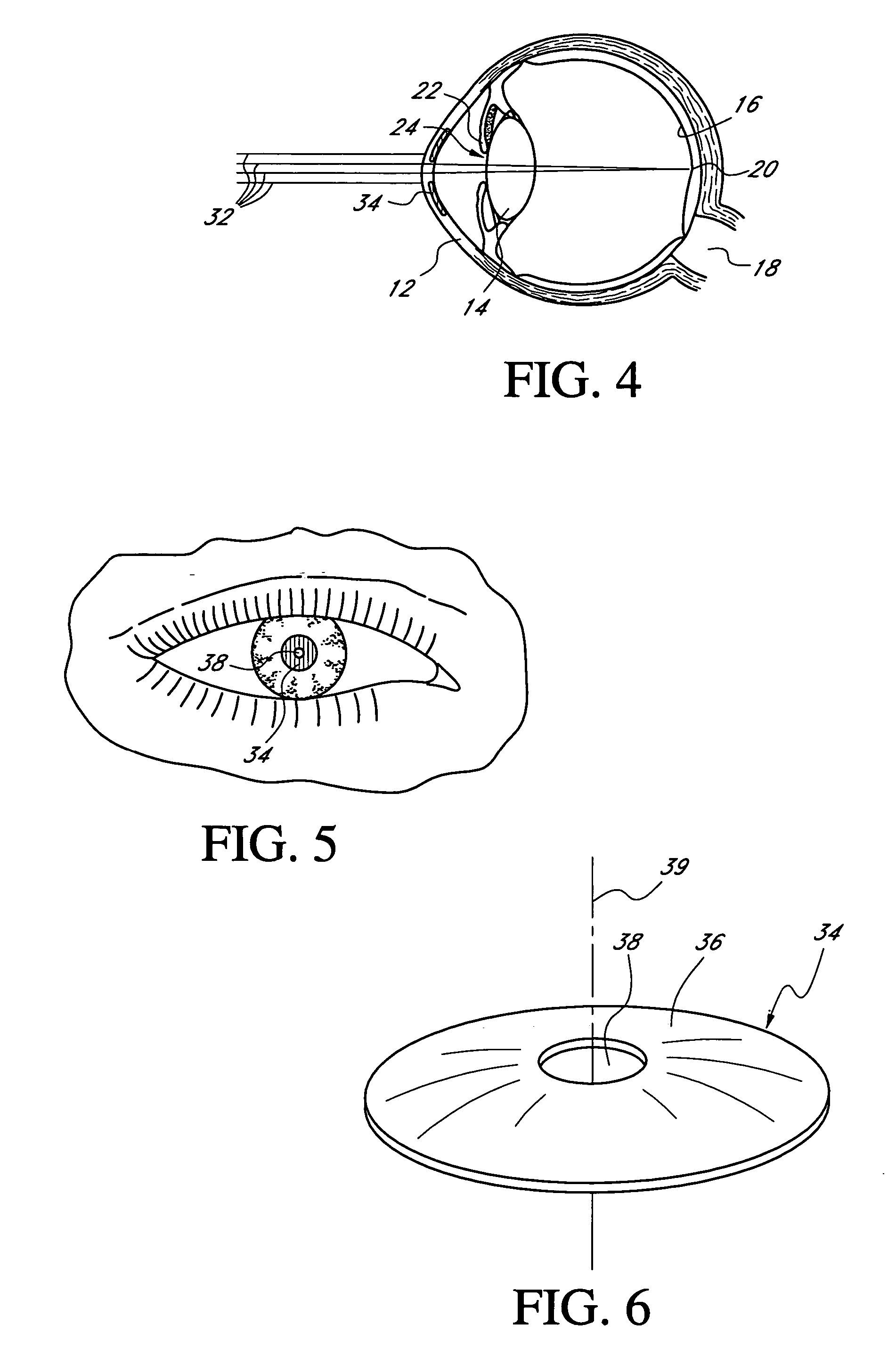
[0081] This application is directed to ocular devices and, more particularly, to corneal inlays and other ocular implant devices with a locator structure that indicates the location of the implanted ocular device and / or facilities removal of the ocular device from the eye. One ocular implant for which these arrangements are particularly well suited includes an inlay or mask that employs pin-hole vision correction, although some of the other devices and applications in which a locator structure could be used are discussed below. The ocular devices may be applied to the eye in any manner and in any location and can be used alone or in combination with other ocular devices, e.g., with contact lenses or intraocular lenses.

I. Overview of Pin-Hole Vision Correction

[0082] As discussed above, mask that has a pinhole aperture may be used to improve the depth of focus of a human eye. As discussed above, presbyopia is a problem of the human eye that commonly occurs in older human adults whe...


PUM


Abstract

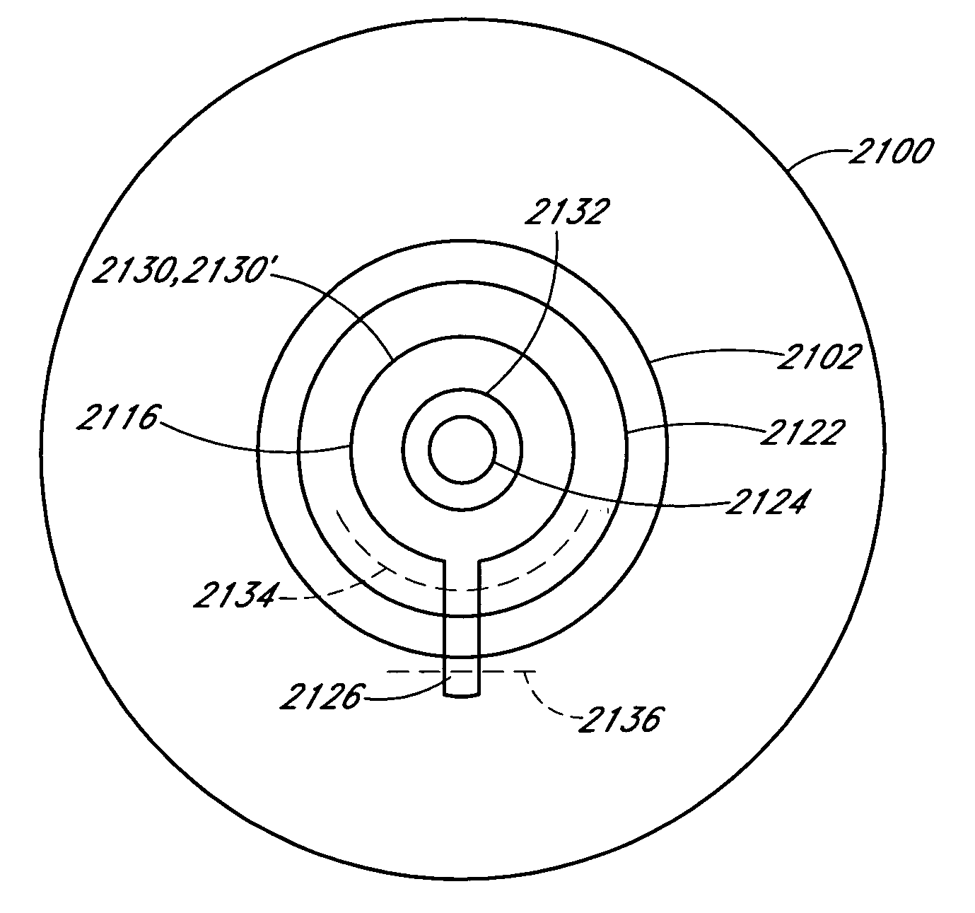
A therapeutic ocular inlay for treatment of one or more vision defects including a locator structure or depth marker to facilitate location of the inlay post-implant. The locator structure or marker extends at least partially outside a pupil region. The depth or layer at which the inlay is implanted can be determined by locating the depth marker without requiring incisions with the pupil region. The locator structure can be substantially invisible under casual observation, however can be provided with enhanced optical contrast characteristics under selected viewing conditions. The locator is thus unobtrusive, however can be readily located in a clinical setting, for example with artificial UV illumination. The locator can be connected to, e.g., integrally formed with, the inlay or may be a separate component provided in combination with the inlay.

Description

BACKGROUND OF THE INVENTION [0001] 1. Field of the Invention [0002] This application relates to ocular devices and, more particularly, to corneal inlays and other ocular implant devices with an unobtrusive locator structure that indicates the location of (e.g., the depth of) the ocular device within the eye when implanted. [0003] 2. Description of the Related Art [0004] The healthy human eye is capable of receiving incident light from a range of viewing distances and appropriately refracting the incident light for proper focus at the retina such that the person has a clear view of the objects. The cornea and crystalline lens interact in a cooperative manner to provide this refraction. The healthy eye adjusts its refractive characteristics to provide the person with clear focused vision of objects both near and distant. This adjustment is normally provided by ciliary muscles attached to the lens that change the shape of the lens when the muscles flex. This process of adjusting is com...

Claims


Application Information

Patent Timeline
IPC IPC(8): A61F9/013A61F2/14
CPCA61F2/145A61F2/16A61F2250/0098A61F9/00834A61F2250/0097A61F9/0017A61F2/15A61F9/007
Inventor SILVESTRINI, THOMAS A.
Owner ACUFOCUS
Learn More