
Method of making a catheter balloon using a polyimide covered mandrel

Inactive Publication Date: 2005-04-12
ABBOTT CARDIOVASCULAR
View PDF21 Cites 26 Cited by
  • Summary
  • Abstract
  • Description
  • Claims
  • Application Information

AI Technical Summary

Benefits of technology

The mandrel jacket prevents or inhibits corrosion of the metallic core of the mandrel during the formation of the fluoropolymeric tube. Corrosive species are produced by the fluoropolymeric material during high temperature heating thereof, thus resulting in a highly corrosive environment at the high temperatures used to fuse sections of the wrapped sheet together. The mandrel jacket protects the metallic core of the mandrel from the highly corrosive environment which would otherwise corrode metals such as stainless steel or carbon steel used to form the metallic core of the mandrel. The corrosion typically includes affects such as oxidation, discoloration, flaking and loss of mechanical properties. Such corrosion makes it difficult to remove the fluoropolymeric tube from the mandrel without damaging the fluoropolymeric tube, and requires frequent disposal of the mandrel.
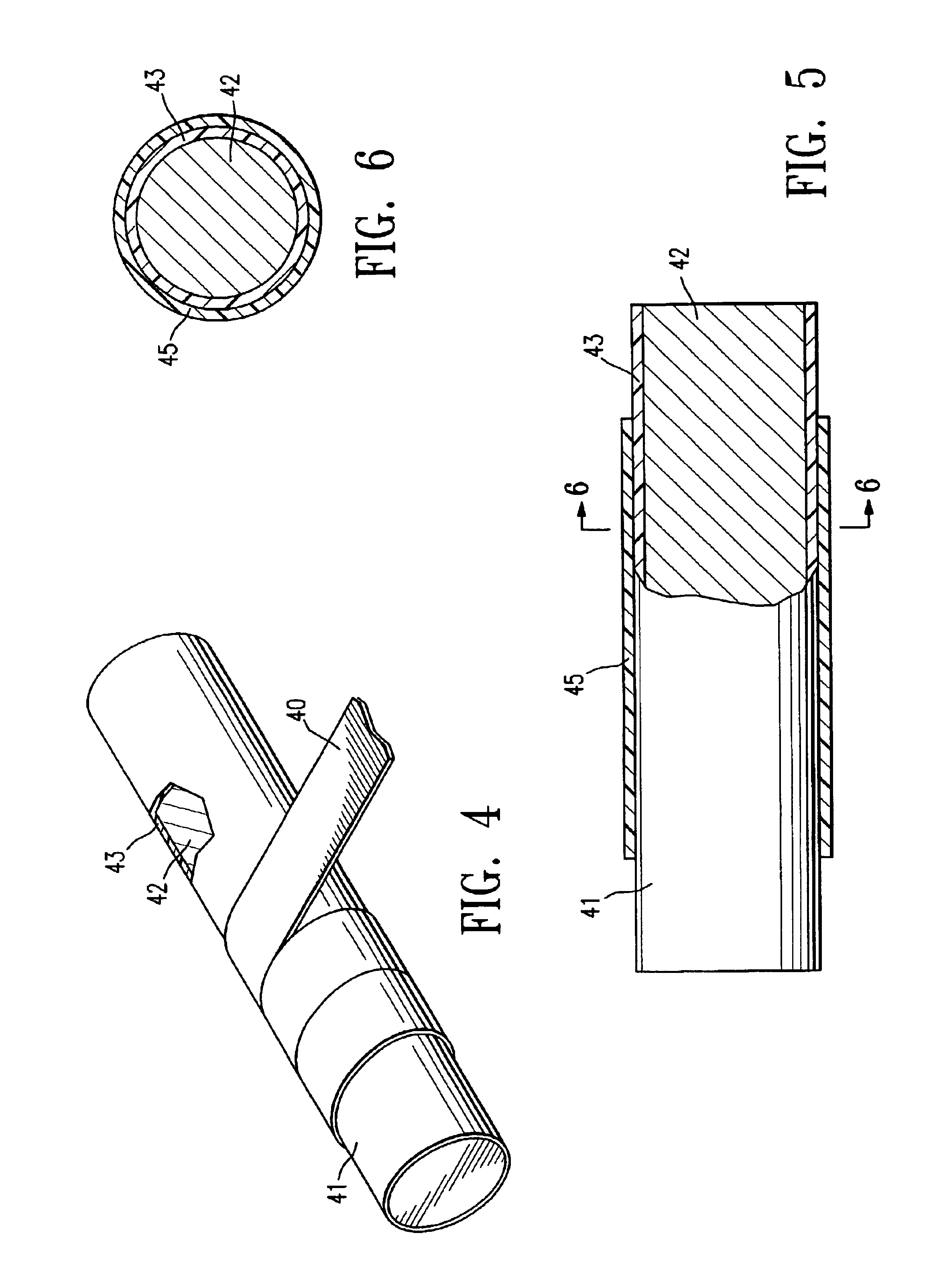
The polymeric material forming the jacket is dimensionally stable at the elevated temperatures used during formation of the fluoropolymeric tube, and specifically during high temperature fusion (i.e., thermal) bonding of the wrapped sheet of fluoropolymeric material to form a fluoropolymeric tube. Thus, the dimensions of the jacket do not change significantly during the heating of the wrapped fluoropolymeric material. Preferably, the outer diameter and length of the jacket are substantially unchanged (i.e., a change of about 0% to about 10%) during the heating of the fluoropolymeric material to form the fluoropolymeric tube. The inner diameter of the resulting fluoropolymeric tube is determined by the outer diameter of the mandrel jacket. Consequently, the dimensionally stable jacket facilitates production of a fluoropolymeric tube having a desired inner diameter.
The polymeric material forming the jacket is preferably a high temperature material having a glass transition temperature (Tg) of about 350° C. to about 450° C., and most preferably about 390° C. to about 420° C. The jacket thus has excellent dimensional stability at the processing temperature of the fluoropolymeric material. In one embodiment, the polymeric material forming the jacket is selected from the group consisting of thermoset polyimide, and a thermoplastic polyimide. The polyimide materials have relatively high glass transition temperatures. Additionally, the polyimide materials have a high abrasion resistance and a high modulus which are maintained at elevated temperature. In a presently preferred embodiment, the jacket comprises a thermoset polyimide, due to the high glass transition temperature of the thermoset polyimide. The thermoset polyimide has a very high glass transition temperature of approximately 390° C. to about 420° C., more specifically about 400° C. to about 410° C. (as measured by differential scanning calorimetry (DSC). Additionally, the thermoset polyimide has excellent dimensional stability at the fluoropolymer fusing temperature of about 370° C. for the duration of the heat treatment, e.g., about 20 to about 30 minutes. Specifically, the thermoset polyimide is crosslinked, and thus has high dimensional stability at or near the glass transition temperature of the polyimide. As a result, the polyimide tube maintains thin-walled, controlled dimensions during formation of the fluoropolymeric tube. Thermoplastic polyimide, such as Aurum available from Mitsui Toatsu Chemical, Inc., which has a Tg of about 230° C. to about 270° C., may also be used, but is less preferred than the more highly dimensionally stable thermoset polyimide. Thus, the mandrel jacket material has high dimensional stability, and specifically has a glass transition temperature above the processing temperature of the fluoropolymeric material, unlike polymeric materials such as polytetrafluoroethylene and silicone.
The method of the invention prevents or inhibits corrosion of the metallic core of the mandrel used in forming a polymeric tubular medical device or component. Moreover, the method facilitates removal of the resulting polymeric tube from the mandrel without damaging the polymeric tube, and provides a tube having a desired inner diameter. These and other advantages of the invention will become more apparent from the following detailed description and accompanying exemplary figures.

Problems solved by technology

Corrosive species are produced by the fluoropolymeric material during high temperature heating thereof, thus resulting in a highly corrosive environment at the high temperatures used to fuse sections of the wrapped sheet together.
The corrosion typically includes affects such as oxidation, discoloration, flaking and loss of mechanical properties.
Such corrosion makes it difficult to remove the fluoropolymeric tube from the mandrel without damaging the fluoropolymeric tube, and requires frequent disposal of the mandrel.

Method used


Image

  • Method of making a catheter balloon using a polyimide covered mandrel
  • Method of making a catheter balloon using a polyimide covered mandrel
  • Method of making a catheter balloon using a polyimide covered mandrel

Examples


Embodiment Construction

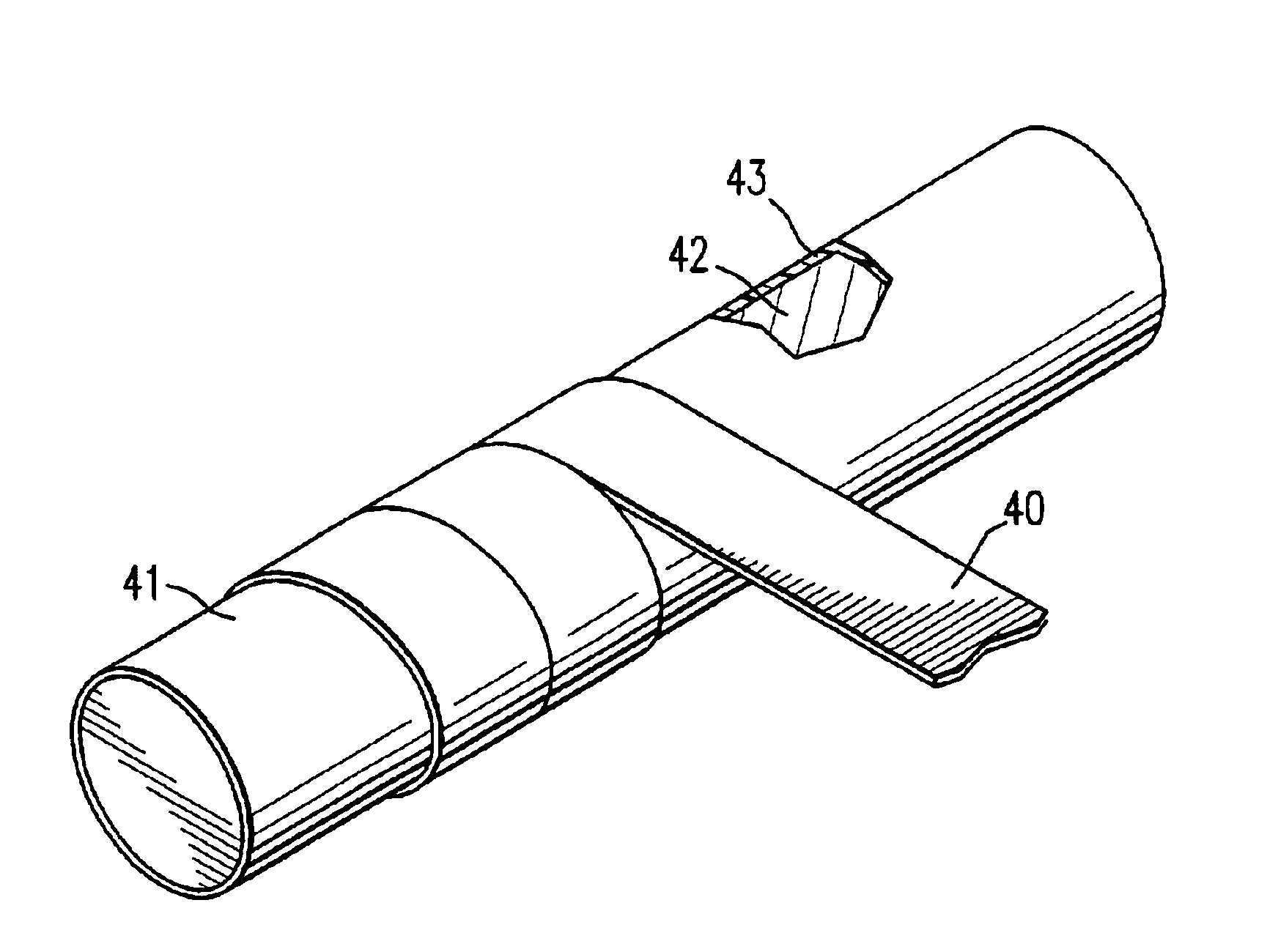
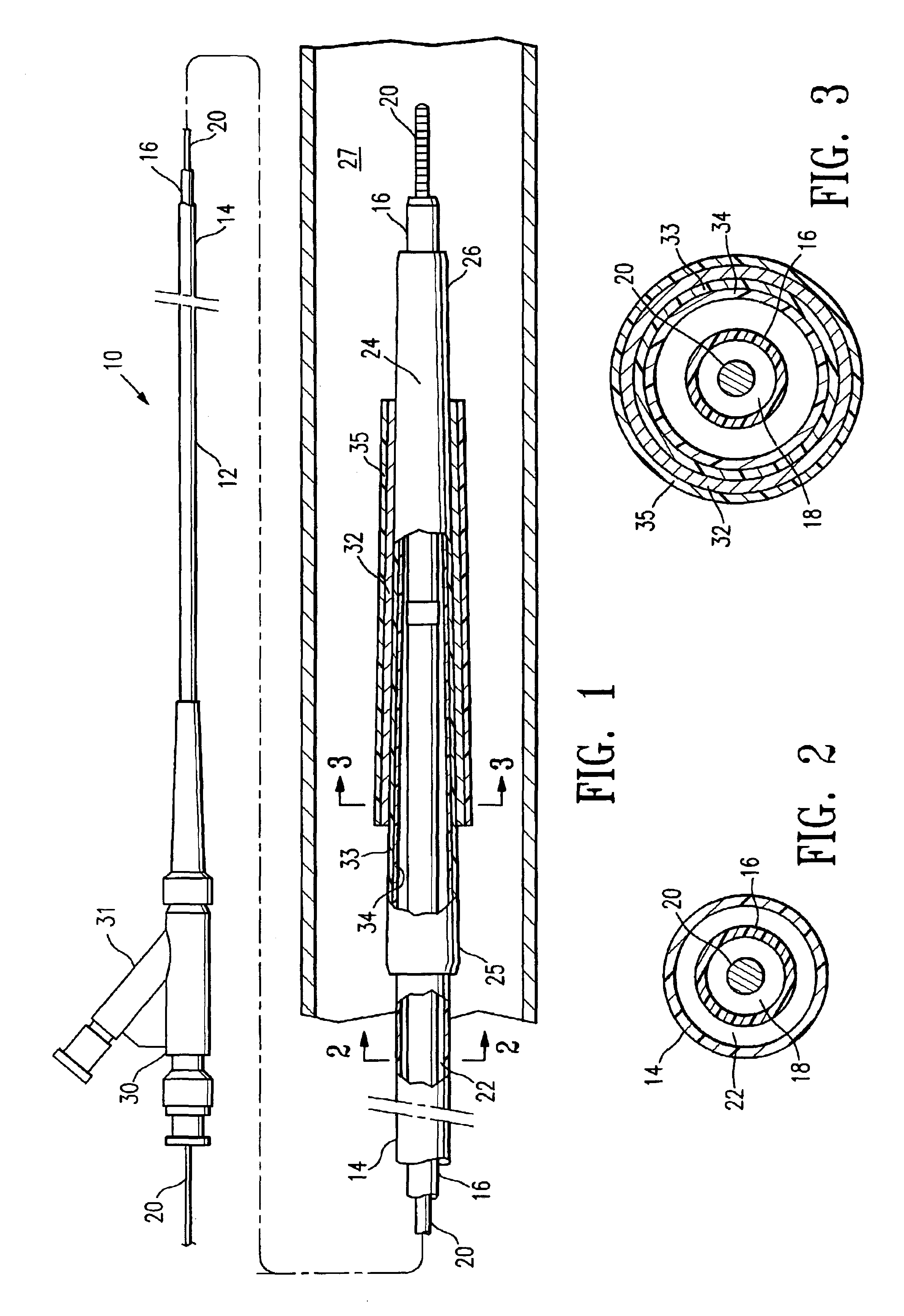
FIG. 1 illustrates an over-the-wire type stent delivery balloon catheter 10 embodying features of the invention. Catheter 10 generally comprises an elongated catheter shaft 12 having an outer tubular member 14 and an inner tubular member 16. Inner tubular member 16 defines a guidewire lumen 18 configured to slidingly receive a guidewire 20, and the coaxial relationship between outer tubular member 14 and inner tubular member 16 defines annular inflation lumen 22, as best illustrated in FIG. 2 showing a transverse cross sectional view of the distal end of the catheter shown in FIG. 1, taken along line 2—2. An inflatable balloon 24 disposed on a distal section of catheter shaft 12 has a proximal skirt section 25 sealingly secured to the distal end of outer tubular member 14 and a distal skirt section 26 sealingly secured to the distal end of inner tubular member 16, so that its interior is in fluid communication with inflation lumen 22. An adapter 30 at the proximal end of catheter sh...


PUM

PropertyMeasurementUnit
Temperatureaaaaaaaaaa

Abstract

A method of making a catheter balloon or other tubular medical device or component, in which a sheet of polymeric material is wrapped on a mandrel and heated to fuse sections of the wrapped sheet together to form a tube. The mandrel has a metallic core and a jacket on an outer surface of the metallic core, and the wrapped sheet of polymeric material is heated without corroding the metallic core of the mandrel. In a presently preferred embodiment, the sheet is formed of a fluoropolymeric material, and the resulting fluoropolymeric tube forms at least a layer of a catheter balloon.

Description

BACKGROUND OF THE INVENTIONThis invention generally relates to medical devices, and particularly to intracorporeal devices for therapeutic or diagnostic uses such as balloon catheters, and vascular grafts.In percutaneous transluminal coronary angioplasty (PTCA) procedures, a guiding catheter is advanced until the distal tip of the guiding catheter is seated in the ostium of a desired coronary artery. A guidewire, positioned within an inner lumen of a dilatation catheter, is first advanced out of the distal end of the guiding catheter into the patient's coronary artery until the distal end of the guidewire crosses a lesion to be dilated. Then the dilatation catheter having an inflatable balloon on the distal portion thereof is advanced into the patient's coronary anatomy, over the previously introduced guidewire, until the balloon of the dilatation catheter is properly positioned across the lesion. Once properly positioned, the dilatation balloon is inflated with fluid one or more ti...

Claims


Application Information

Patent Timeline
IPC IPC(8): A61L29/00A61L29/04A61M25/16B29D23/00
CPCA61L29/041B29D23/001C08L27/18
Inventor BLANKENSHIP, DELMA M.LEE, JEONG S.
Owner ABBOTT CARDIOVASCULAR
Learn More