Intervertebral prosthetic disc

a prosthetic disc and intervertebral technology, applied in the field of intervertebral prosthetic discs, can solve the problems of limiting the patient's activities, limiting the range of motion of the spine, pain to the patient, etc., and achieves the effects of reducing or eliminating complications, increasing the surface area of the system, and less invasiv

Active Publication Date: 2006-08-10
DEPUY SYNTHES PROD INC
View PDF99 Cites 228 Cited by
  • Summary
  • Abstract
  • Description
  • Claims
  • Application Information

AI Technical Summary

Benefits of technology

[0015] In yet another embodiment, the invention includes a intervertebral prosthetic disc system that includes an intervertebral prosthetic disc and at least one spring element. Spring elements can thus be used, for example, to increase the surface area of the system and to provide additional support. Thus, in one embodiment, the intervertebral prosthetic disc can be smaller than a disc used for an anterior surgical operation and therefore the system can be used for posterior or posterior-lateral installation of the intervertebral prosthetic disc.
[0016] A posterior or a posterior-lateral procedure to intervertebral disc replacement is typically less invasive than an anterior procedure. Complications related to anterior procedures can be reduced or eliminated by practicing the present invention. In some embodiments, the services of a vascular surgeon needed to access the intervertebral disc space are reduced or eliminated.
[0017] By practicing the present invention, a surgeon using a guidewire placement method can obtain precise location of a prosthetic disc's endplates relative to the vertebral bodies. The present invention can provide the surgeon with the ability to finely adjust the location of the intervertebral disc to ensure proper disc function. By practicing the invention, pieces of an endplate can be connected with relative ease within the intervertebral space. As a result, smaller devices can be inserted through smaller exposures and assembled in vivo.
[0018] The intervertebral prosthetic discs of the present invention can have a generally larger surface area for contact with the vertebral bone endplates than would be expected in a device inserted using a posterior or posterior-lateral approach. A generally larger surface area for contact with the vertebral bone endplates can reduce or eliminate subsidence of the intervertebral prosthetic disc.
[0019] The intervertebral prosthetic discs of the present invention can provide for translation motion as well as rotation motion when surgically installed in the spinal column. Practice of the present invention can also expand patient indications that can be treated using the herein-described intervertebral prosthetic disc by restoring spinal stability without having to rely on the natural anatomy. For example, practice of the present invention can restore spinal stability without having to rely on the facets of the spine to limit motion. In one embodiment, spring elements can be used to resist excessive rotation and translation.

Problems solved by technology

When a disc, or a portion of a disc, wears out or is injured, the disc cannot function normally and the failed disc can cause pain to a patient or limit the patient's activities.
Spinal fusion can be effective in reducing pain, but it limits the range of motion of the spine and it can result in transfer of extra stress to discs above and below the fusion site.

Method used


Image

  • Intervertebral prosthetic disc
  • Intervertebral prosthetic disc
  • Intervertebral prosthetic disc

Examples


Embodiment Construction

[0041] The foregoing and other objects, features and advantages of the invention will be apparent from the following more particular description of preferred embodiments of the invention, as illustrated in the accompanying drawings in which like reference characters refer to the same parts throughout the different views. The drawings are not necessarily to scale, emphasis instead being placed upon illustrating the principles of the invention.

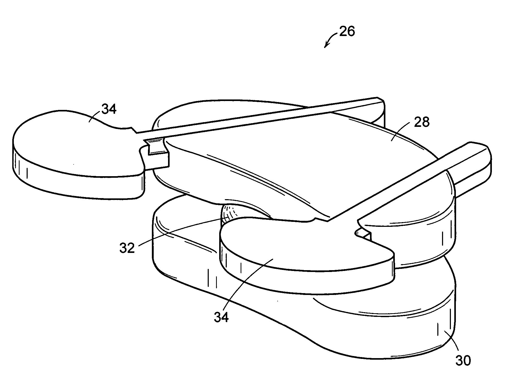
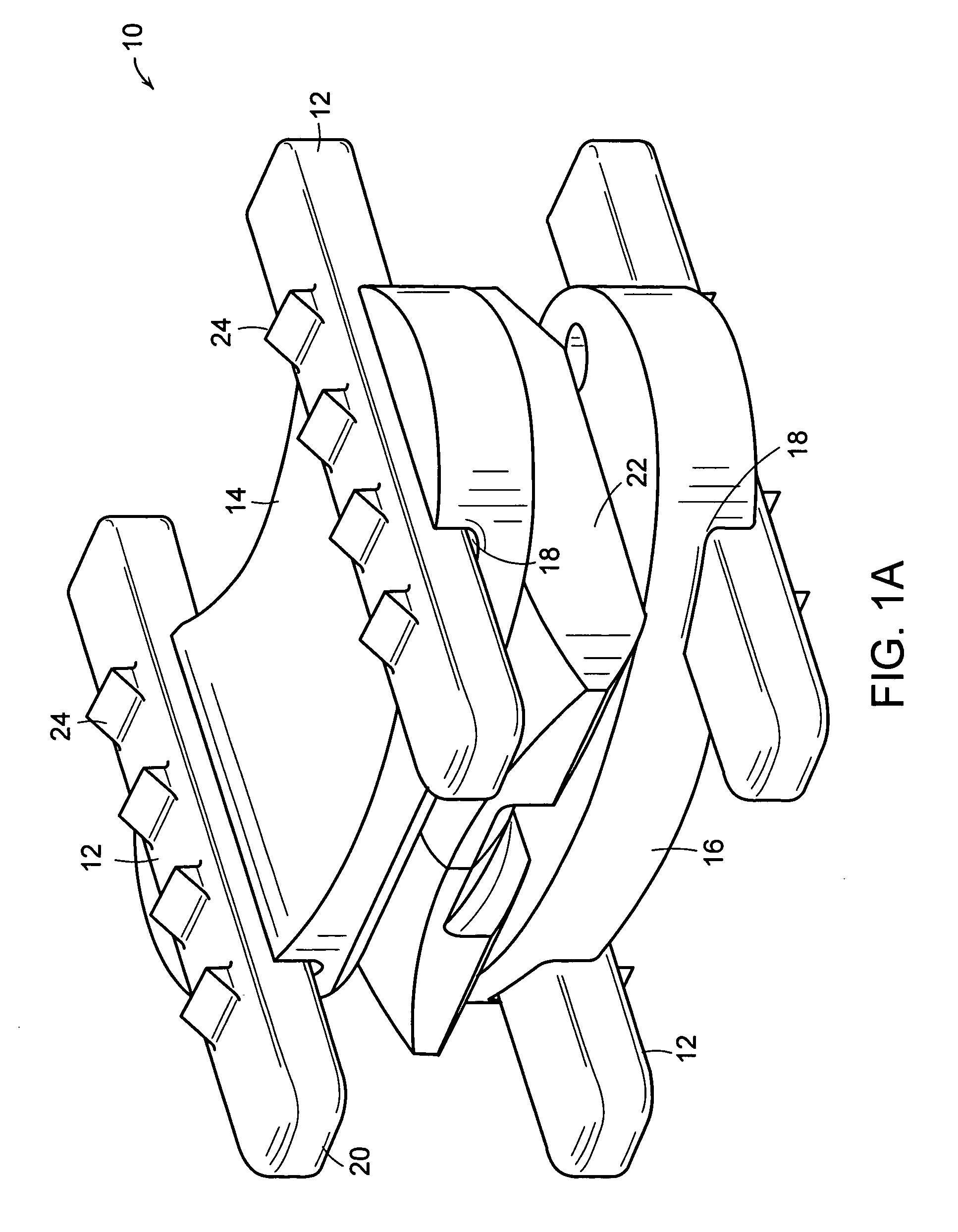
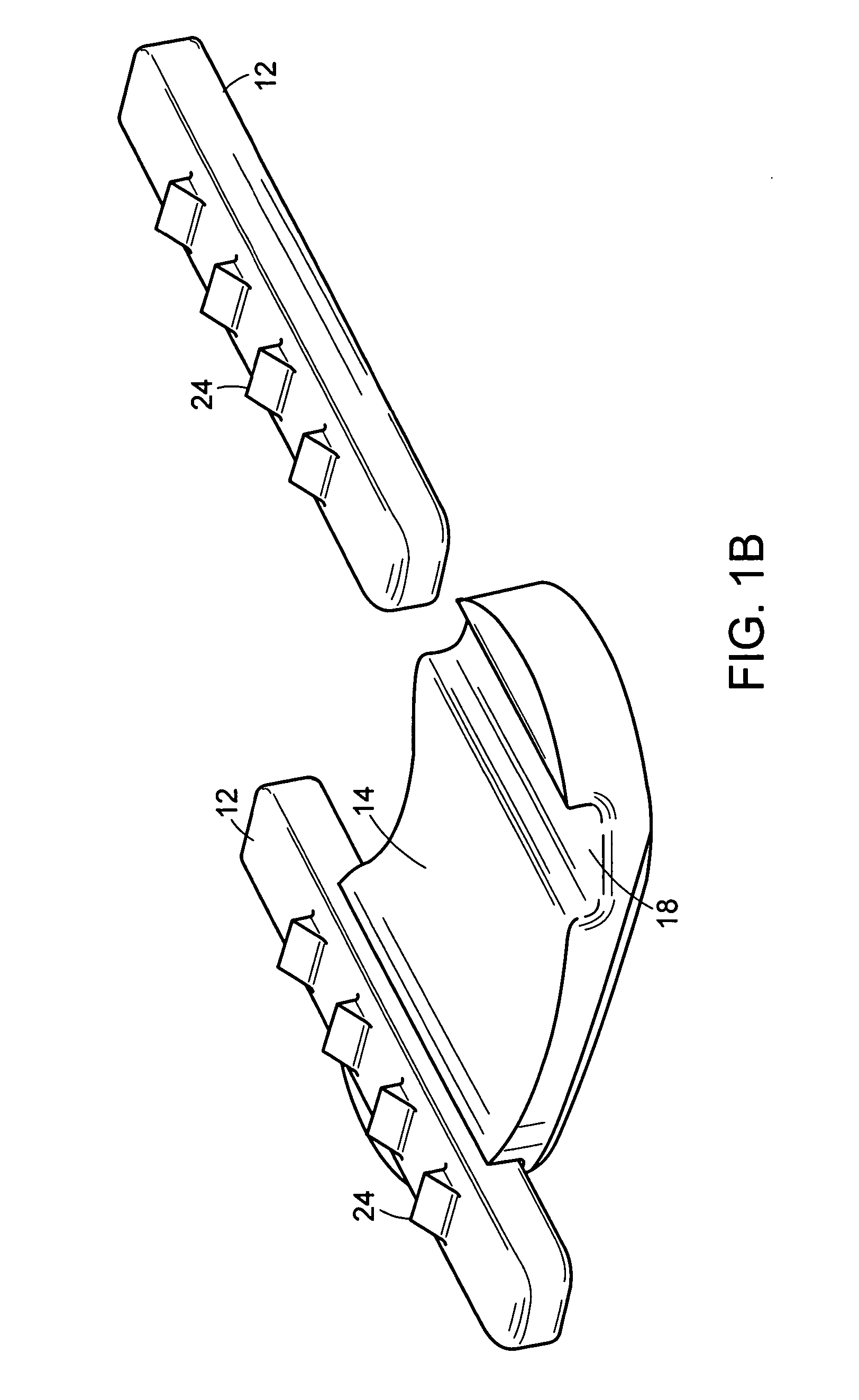
[0042] The present invention includes an intervertebral prosthetic disc. In one embodiment, an intervertebral prosthetic disc includes a superior endplate; an inferior endplate; and at least one protrusion element, wherein at least one of the superior endplate and the inferior endplate is adapted to receive the protrusion element. In another embodiment, the present invention includes an intervertebral prosthetic disc which includes a superior endplate; an inferior endplate; a core positioned between the superior endplate and the inferior endpla...


PUM

PropertyMeasurementUnit
resilientaaaaaaaaaa
movementaaaaaaaaaa
elasticaaaaaaaaaa

Abstract

The present invention includes intervertebral prosthetic devices and methods for installing intervertebral prosthetic devices into an intervertebral space. In one embodiment, an intervertebral prosthetic disc includes a superior endplate; an inferior endplate; and at least one protrusion element, wherein at least one of the superior endplate and the inferior endplate is adapted to receive the protrusion element. In another embodiment, the invention includes an intervertebral prosthetic disc having a superior endplate including a core retaining member; an inferior endplate including a core retaining member; and an asymmetric core positioned between the superior endplate and the inferior endplate, wherein the superior endplate and the inferior endplate are adapted to accommodate the core. The present invention also includes an intervertebral prosthetic disc system that includes an intervertebral prosthetic disc and at least one spring element.

Description

BACKGROUND OF THE INVENTION [0001] The human spinal column consists of discrete, sequentially coupled bones, i.e., vertebrae, cushioned by cartilaginous spacers, i.e., intervertebral discs, disposed between opposing vertebral bone endplates. Intervertebral discs are generally elastic, allowing the spine to retain a high degree of flexibility. When a disc, or a portion of a disc, wears out or is injured, the disc cannot function normally and the failed disc can cause pain to a patient or limit the patient's activities. Therefore, surgery is often recommended when an intervertebral disc fails, for example, due to disease, infection, deformity, or fracture. Surgery can sometimes help to reduce attendant pain and restore at least some level of activity to the patient. Surgery can include implantation of an artificial disc or other prosthetic devices that restore the height of the spinal column and a natural angle between the adjacent vertebrae. For example, surgery can include spinal fu...

Claims


Application Information

Patent Timeline
Patent Type & Authority Applications(United States)
IPC IPC(8): A61F2/44
CPCA61F2/442A61F2310/00796A61F2002/2817A61F2002/30092A61F2002/30224A61F2002/30365A61F2002/30387A61F2002/30433A61F2002/305A61F2002/30563A61F2002/30565A61F2002/30574A61F2002/30579A61F2002/30594A61F2002/30604A61F2002/30649A61F2002/30662A61F2002/30769A61F2002/30841A61F2002/30878A61F2002/30909A61F2002/443A61F2002/448A61F2210/0014A61F2220/0025A61F2220/0033A61F2220/0041A61F2230/0069A61F2310/00017A61F2310/00023A61F2310/00029A61F2310/00203A61F2310/00239A61F2310/00293A61F2310/00365A61F2/4425
Inventor BARTISH, CHARLES M. JR.TORRES, KATHERINEHAWKINS, J. RILEYKWAK, S. DANIEL
Owner DEPUY SYNTHES PROD INC
Why Eureka
Try Eureka