Headrest system for resting and sleeping and resting mode
A headrest and forehead technology, applied to other seating furniture, etc., can solve the problems of different widths, user discomfort, and small moving range
- Summary
- Abstract
- Description
- Claims
- Application Information
AI Technical Summary
Problems solved by technology
Method used
Image

Examples
Embodiment 1
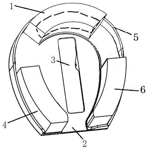
[0078] Soft and elastic material such as sponge is arranged in its forehead pillow 1 inside, and the forehead pillow 1 is arranged on the base 2 . Rib 5 is arranged on the base 2, and the forehead pillow leans against the rib 5, and there is a large hole 3 in the middle of the base 2 for nose breathing. The contact position of head and forehead pillow 1 during use is forehead 34 (see Figure 9 between the dotted line and the hair), and certain sensitive parts of the head and face are excluded, figure 1 The dotted line part in the middle dotted line part forehead pillow 1 is the contact part of forehead pillow and head; These sensitive parts are brow bone, eyes and nose. The sidewall 5 is used to prevent the forehead pillow and the face pillow from falling down, although the forehead pillow and the face pillow can also be designed as anti-dumping without the sidewall, but in this case, the forehead pillow will become wider, which is much larger than that with the sidewall, whi...
Embodiment 2
[0082] A forehead pillow 7, than figure 1 The forehead pillow 1 will be big, and the contact position of the head and the forehead pillow 7 during use is near the left eye corner to the forehead and then to the right eye corner; the sensitive parts of the head and face are excluded; these sensitive parts are browbones, eyes, and nose. The stress-bearing part of the head is Figure 10 The area between the dotted line and the hair. The forehead pillow 7 surrounds a depression 8, so that the forehead pillow does not need to touch the brow bone, eyes, and keeps relatively large contact with the head during use. other structures and figure 1 The corresponding part is the same. 2 has a big hole in the middle for the nose to breathe. 9 is the contact part between the forehead pillow 7 and the head after being compressed, that is, the forehead pillow part within the dotted line.
Embodiment 3
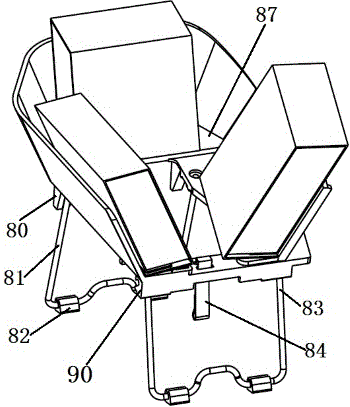
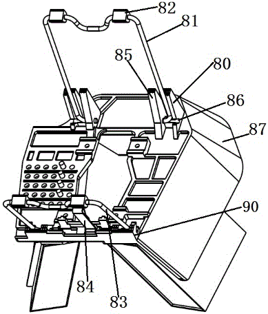
[0084] The base 14 of this embodiment is provided with a forehead pillow 10 and a left face pillow 12, and these two pillows all lean against outwardly inclined ribs 13, and the ribs prevent these two pillows from falling outwards. The small base 22 is placed on the base 14, the bottom of the small base 22 has a Velcro 25, the right half of the base 14 has a Velcro 20 complementary to the Velcro 25, the small base 22 passes through the Velcro 25, 20 is fixed on the base 14 and will not fall off. In addition, the bottom of the small base 22 has 4 columns such as 21, and the right half of the base 14 has a number of regularly arranged holes such as 19, and the insertion of the cylinder 21 into the hole 19 can prevent the small base 22 from falling outwards. In theory, only one pillar is needed. The small base 22 can insert the bottom cylinder in different holes of the base 14 to change the relative position of the two bases. Cylinders, holes and hook and loop are a good soluti...
PUM
 Abstract
Description
Claims
Application Information
 - R&D
- Intellectual Property
- Life Sciences
- Materials
- Tech Scout
- Unparalleled Data Quality
- Higher Quality Content
- 60% Fewer Hallucinations
Browse by: Latest US Patents, China's latest patents, Technical Efficacy Thesaurus, Application Domain, Technology Topic, Popular Technical Reports.
© 2025 PatSnap. All rights reserved.Legal|Privacy policy|Modern Slavery Act Transparency Statement|Sitemap|About US| Contact US: help@patsnap.com