Energy-saving and environment-friendly gas wall-hung boiler combustion system

A gas wall-hung boiler and combustion system technology, which is applied to gas fuel burners, burners, and combustion methods, can solve the problems of inability to burn gas instantly, large vibration of gas wall-hung boilers, and large hydrogen and methane emissions. Smooth smoke exhaust, low cost, and large air intake

Active Publication Date: 2018-07-13
黎素云
View PDF9 Cites 0 Cited by
  • Summary
  • Abstract
  • Description
  • Claims
  • Application Information

AI Technical Summary

Problems solved by technology

[0002] 1. At present, the combustion heat exchanger of the gas wall-hung boiler is installed upside down, that is, the combustion bottom above the combustion heat exchanger discharges the flue gas, and its exhaust port is flat and small. Since the combustion chamber of the combustion heat exchanger is on the top, When it burns, the flame and smoke go up, but when it burns, the smoke exhaust port of the combustion heat exchanger is set at the bottom, and the smoke exhaust method can only go from top to bottom. In the principle of heat, hot gas and hot smoke are Going up, forming the opposite smoke exhaust method, the combustion chamber is sealed, the gas enters the combustion chamber from above the combustion chamber, ignites and burns in the combustion chamber, the firepower is too concentrated in the combustion chamber, and the gas burns instantly in the combustion chamber During this period, a large amount of expanding hot air flow will be generated. The smoke exhaust port of the combustion heat exchanger is set at the bottom and the smoke exhaust port is too small. In the gas channel, the firepower in the lower section is insufficient, the heat is small, and the heating is insufficient, resulting in low heat transfer efficiency and low heat conversion rate of the water flow in the lower section of the combustion heat exchanger; 2. In the continuous combustion process, repeated 3. During the instant combustion of the combustion chamber of the combustion heat exchanger, a fireball will be formed, and part of the gas cannot be fully burned instantly, resulting in hydrogen , carbon monoxide, methane emissions are large, causing air pollution; 4, the existing gas full premixing technology gas and air mixing, all use Venturi tube to supply fuel mixing technology, but due to the large volume of the Venturi tube, the arrangement The air inlet area of ​​the fan is occupied at the fan port, resulting in a decrease in the air intake efficiency of the fan, poor premixing effect, too thick a mixture, and low efficiency

Method used


Image

  • Energy-saving and environment-friendly gas wall-hung boiler combustion system
  • Energy-saving and environment-friendly gas wall-hung boiler combustion system
  • Energy-saving and environment-friendly gas wall-hung boiler combustion system

Examples


example 1

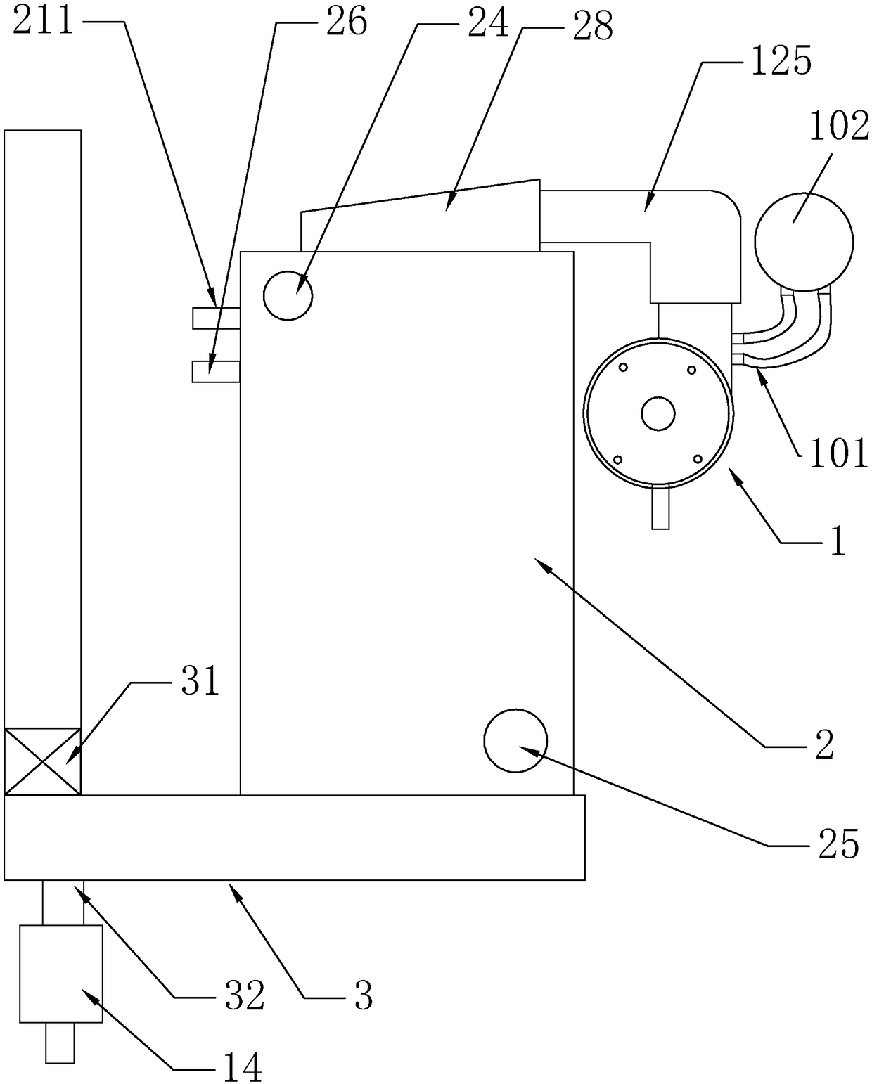
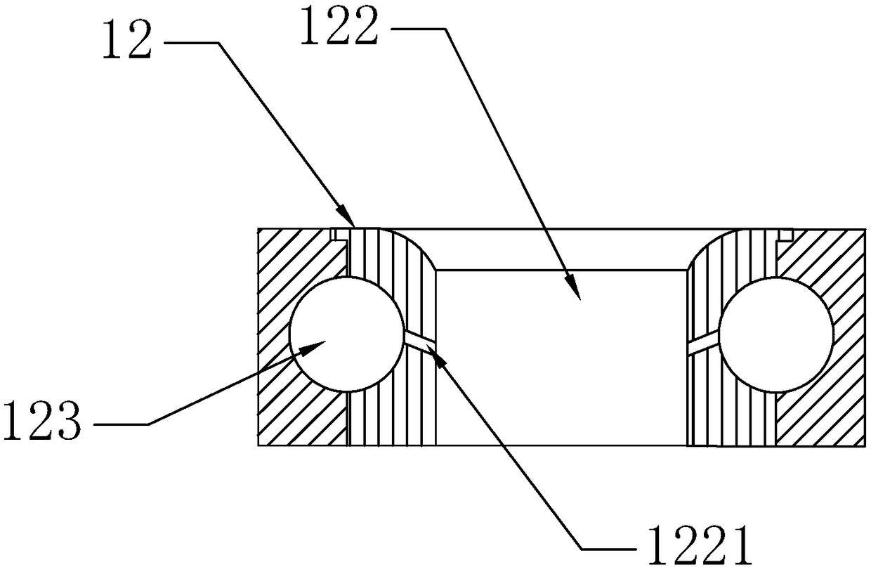
[0036] When the combustion heat exchanger 2 is about to burn and heat water, the water valve is opened to allow the water flow to enter from the water inlet 24, the exhaust fan 31 works, the blower fan 11 starts, and the gas enters the gas circulation ring hole 123 from the gas inlet hole 121, and passes through the gas injection hole. The hole 1221 sprays out to the through hole 12, and is inhaled into the inner cavity of the fan through the fan 11. At the same time, the outside wind is sucked into the inner cavity of the fan through the air inlet hole 1241 and the air induction pipe 1242, and the air and gas are mixed by the agitation of the fan 11. Mixing, send the mixed gas into the combustion chamber 21 through the short gas connection pipe 125, ignite and burn through the ignition needle 211 to heat the combustion heat exchanger 2, the burnt fire tail and smoke body go down, pass through the heat exchange channel 22, and then The smoke exhaust port 23 at the bottom discha...

example 2

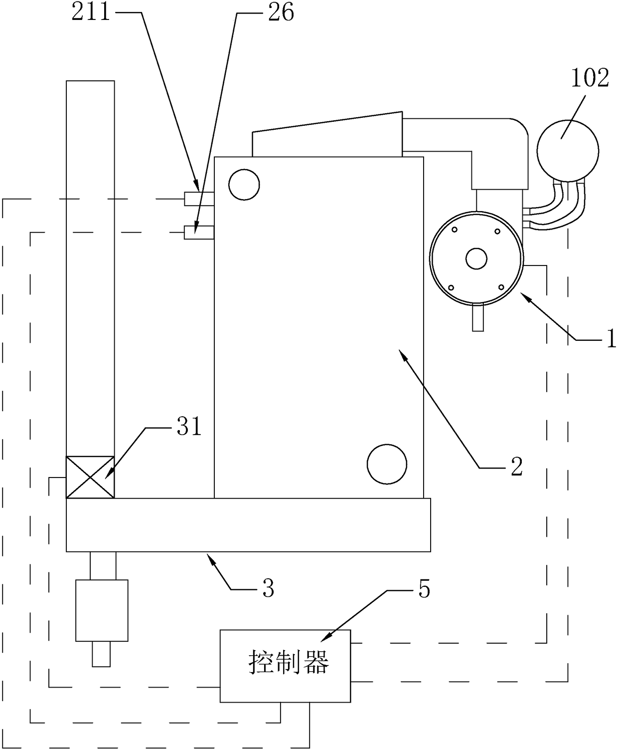
[0038] When the combustion heat exchanger 2 is to burn and heat water, the water valve is opened so that the water flow enters from the water inlet 24, the wind pressure switch 102 sets the wind pressure value for starting the exhaust fan 31, the blower fan 11 is started, and the gas valve is opened to make the gas flow from the gas. The air inlet hole 121 enters the gas circulation ring hole 123, and the gas is ejected to the through hole 12 through the gas injection hole 1221, sucked into the inner cavity of the fan through the fan 11, and also sucks the outside wind through the air inlet hole 1241 and the air duct 1242. In the inner cavity of the blower, the air and gas are mixed by the stirring of the fan 11 wind wheel, and the mixed gas is sent into the combustion chamber 21 through the gas connection short pipe 125, and is ignited and burned by the ignition needle 211 to heat the combustion heat exchanger 2, and the burnt fire tail And the smoke body goes down, passes thr...


PUM


Abstract

The invention discloses an energy-saving and environment-friendly type combustion system of a gas wall-hanging stove. The combustion system of the gas wall-hanging stove comprises an air and gas mixing entering device (1). The air and gas mixing entering device (1) is connected with an inverted combustion heat exchanger (2). A smoke outlet of the inverted combustion heat exchanger (2) is connected with a smoke discharge pipeline body (3) for discharging and conveying smoke. An exhaust fan (31) is arranged on the smoke discharge pipeline body (3). A condensate water drainage opening (32) is formed in the smoke discharge pipeline body (3). The energy-saving and environment-friendly type combustion system is simple in structure, high in practicality, low in cost and convenient to mount and maintain; by means of combined air exhaust of the exhaust fan and a draught fan and an air inducing hood, the circulating speed of air can be increased; by means of increasing of the circulating speed of air, combustion hot air flow can be effectively prevented from flowing back into an air inlet channel, and stove body noise caused by backflow of combustion expansion gas is avoided; and meanwhile heat exchange efficiency is greatly improved.

Description

technical field [0001] The invention and a gas circulation device specifically relate to an energy-saving and environment-friendly gas wall-hung boiler combustion system. Background technique [0002] 1. At present, the combustion heat exchanger of the gas wall-hung boiler is installed upside down, that is, the combustion bottom above the combustion heat exchanger discharges the flue gas, and its exhaust port is flat and small. Since the combustion chamber of the combustion heat exchanger is on the top, When it burns, the flame and smoke go up, but when it burns, the smoke exhaust port of the combustion heat exchanger is set at the bottom, and the smoke exhaust method can only go from top to bottom. In the principle of heat, hot gas and hot smoke are Going up, forming the opposite smoke exhaust method, the combustion chamber is sealed, the gas enters the combustion chamber from above the combustion chamber, ignites and burns in the combustion chamber, the firepower is too co...

Claims


Application Information

Patent Timeline
Patent Type & Authority Patents(China)
IPC IPC(8): F24H9/18F23D14/04F23D14/64F23D14/46
CPCF23D14/04F23D14/46F23D14/64F23D2203/007F24H9/1836
Inventor 黎素云
Owner 黎素云
Why Eureka
Try Eureka