Rotary cultivator

A rotary tiller and knife shaft technology is applied in the field of rotary tillers to avoid misoperation and loss.

Inactive Publication Date: 2016-04-20
NAN COUNTY WEIYE MACHINERY MFG
View PDF6 Cites 0 Cited by
  • Summary
  • Abstract
  • Description
  • Claims
  • Application Information

AI Technical Summary

Problems solved by technology

However, at present, it is mainly human beings who operate the rotary tiller, and misoperation is inevitable.
In this way, how to ensure that the operator can only operate the rotary tiller according to the correct process, so as to avoid unnecessary losses caused by misoperation has become an urgent problem to be solved at present.

Method used


Image

  • Rotary cultivator
  • Rotary cultivator
  • Rotary cultivator

Examples


Embodiment Construction

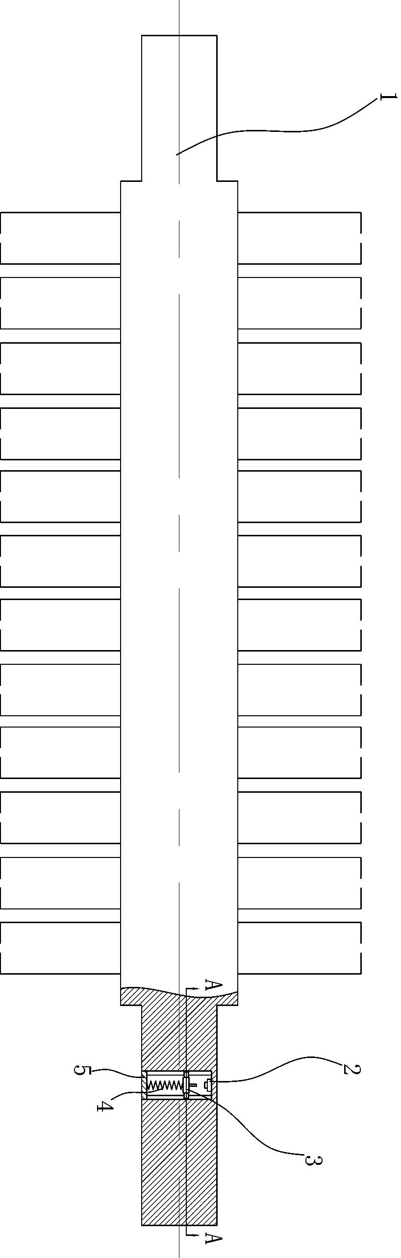
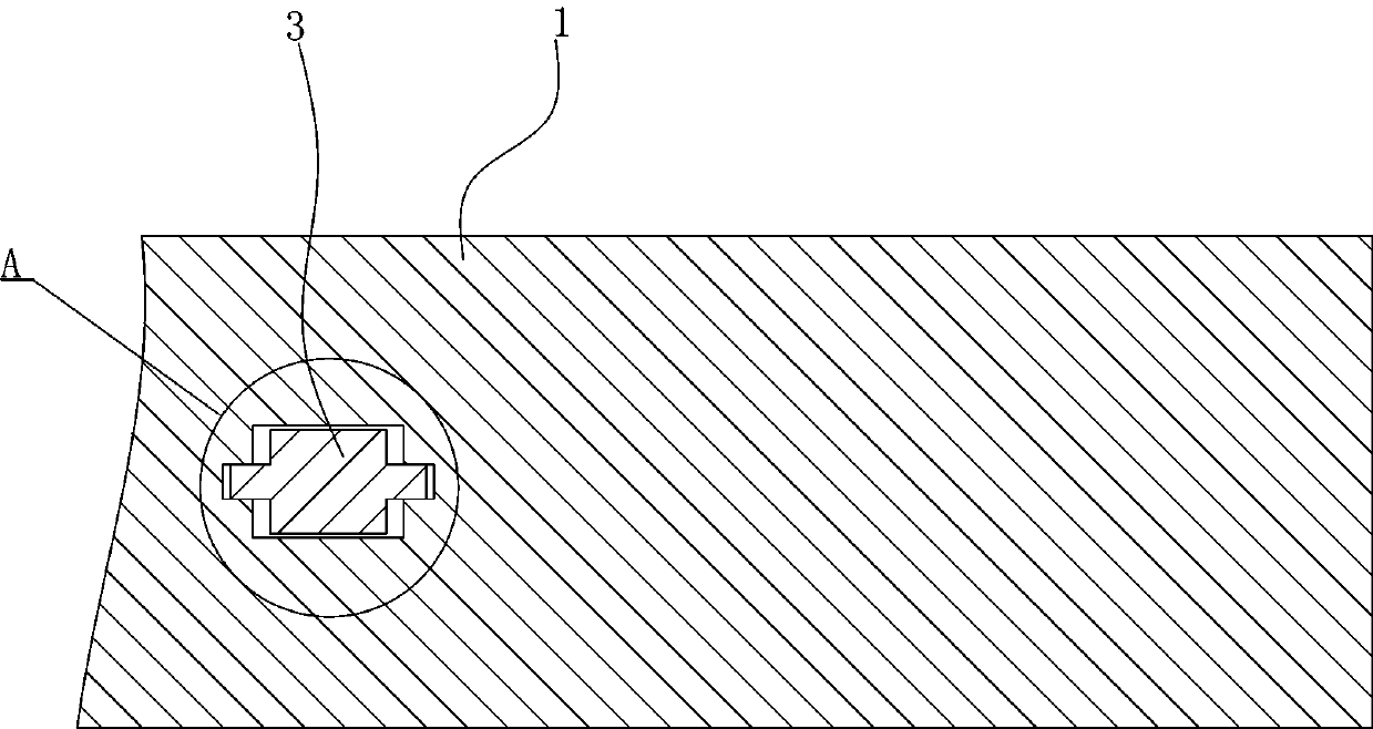
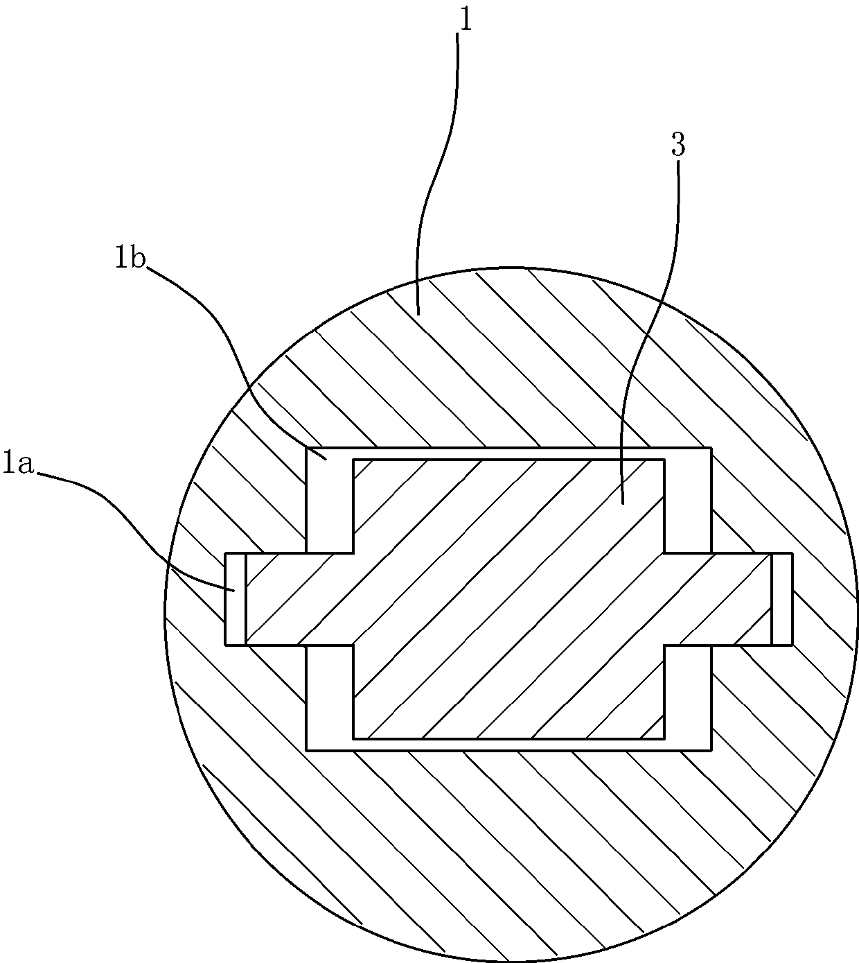
[0011] The specific implementation manner of the present invention will be described in detail below in conjunction with the accompanying drawings. A rotary tiller, comprising a cutter shaft 1, the cutter shaft 1 is provided with a rectangular blind hole 1b, the axis of the blind hole 1b coincides with the radial direction of the cutter shaft 1, and the two opposite sides of the blind hole 1b A chute 1a with a rectangular cross section is provided on the wall. A switch 2 is provided at the center of the bottom surface of the blind hole 1b. A push rod 3 is also arranged in the blind hole 1b, and the push rod 3 is composed of a base 3b, a push rod 3a and a slider 3c. The base 3b is a rectangular block and matches the blind hole 1b. A cylindrical push rod 3a is provided at the center of the top surface of the base 3b, and a cylindrical push rod 3a is provided at the center of the left and right side walls of the base 3b. A slide block 3c, the slide block 3c is matched with the ...


PUM


Abstract

The invention discloses a rotary cultivator. According to the rotary cultivator, a switch (2), an ejector rod (3) and a spring (4) are additionally arranged on a cutter shaft (1) of the rotary cultivator, and sliding blocks (3c) for guiding and sliding grooves (1a) for guiding are further formed between the ejector rod (3) and the cutter shaft (1). When the cutter shaft (1) rotates, the ejector rod (3) is driven to rotate; meanwhile, the ejector rod (3) gradually moves to a button of the switch (2) under the common effect of centrifugal force and interaction between the sliding blocks (3c) and the sliding grooves (1a), and the centrifugal force borne by the ejector rod (3) is increased along with increasing of the rotating speed of the cutter shaft (1). Finally, when the cutter shaft (1) rotates at the rated rotating speed, the switch (2) is switched on through the ejector rod (3) to unlock a lifting system of the cutter shaft (1), and the lifting system of the cutter shaft (1) can be lifted. In this way, the problems that as an operator falsely operates, when the rotating speed of the cutter shaft (1) does not reach the standard, the cutter shaft (1) descends in advance, and a blade is bent or broken are solved, and deadweight losses are avoided.

Description

technical field [0001] The invention relates to the field of tillage machinery, in particular to a rotary tiller. Background technique [0002] A rotary tiller is one. A driven soil tillage machine with rotating cutter teeth as the working part, also known as a rotary tiller. Because of its strong soil crushing ability, one operation can make the soil finely crushed, the soil and fertilizer can be mixed evenly, and the ground can be leveled, which can meet the requirements of dry land sowing or paddy field planting, which is conducive to gaining farming time, improving work efficiency, and making full use of the power of tractors, etc. Advantages, so it is widely used in soil cultivation operations. The use requirements of the rotary tiller, at the beginning of the operation, the rotary tiller should be in the lifting state, first combined with the power output shaft, so that the cutter shaft speed increases to the rated speed, and then lower the rotary tiller, so that the...

Claims


Application Information

Patent Timeline
Patent Type & Authority Applications(China)
IPC IPC(8): A01B33/02A01B33/08A01B33/10
CPCA01B33/021A01B33/08A01B33/103
Inventor 余威
Owner NAN COUNTY WEIYE MACHINERY MFG
Why Eureka
Try Eureka