A photovoltaic module framing machine

A photovoltaic module and framing machine technology, applied in photovoltaic modules, photovoltaic power generation, electrical components, etc., can solve the problems of single solar cells not being able to use power, fixing the surface of photovoltaic panels, and increasing processing costs

Active Publication Date: 2019-11-26
江苏晟木商务服务有限公司
View PDF7 Cites 0 Cited by
  • Summary
  • Abstract
  • Description
  • Claims
  • Application Information

AI Technical Summary

Problems solved by technology

[0002] A single solar cell cannot be directly used as a power source
As a power supply, a number of single cells must be connected in series, parallel and tightly packaged into modules. Photovoltaic modules (also called solar panels) are the core part of solar power generation systems and the most important part of solar power generation systems. Solar energy is converted into electrical energy and sent to the storage battery for storage, or to drive the load to work. However, with the use of micro-inverters, the current source of the photovoltaic module can be directly converted into a voltage source of about 40 volts, which can drive In our daily life, the existing photovoltaic panels cannot be fixed on the surface of the photovoltaic panels when they are framed, and it is easy to cause the photovoltaic panels to bend due to improper operation of the staff when framing the photovoltaic panels, resulting in Photovoltaic panels are damaged, which increases their processing costs and is not conducive to widespread promotion

Method used


Image

  • A photovoltaic module framing machine
  • A photovoltaic module framing machine
  • A photovoltaic module framing machine

Examples


Embodiment Construction

[0014] In order to make the technical means, creative features, goals and effects achieved by the present invention easy to understand, the present invention will be further elaborated below in conjunction with specific embodiments and accompanying drawings, but the following embodiments are only preferred embodiments of the present invention, not all . Based on the examples in the implementation manners, other examples obtained by those skilled in the art without making creative efforts all belong to the protection scope of the present invention.

[0015] Specific embodiments of the present invention will be described below in conjunction with the accompanying drawings.

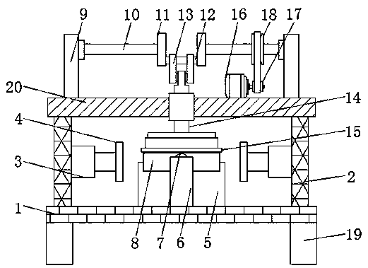
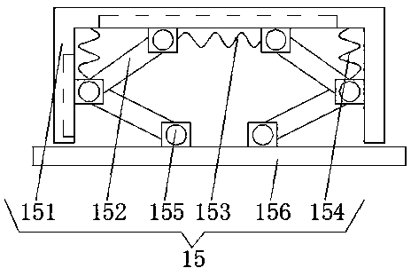
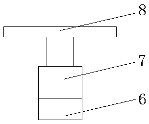
[0016] see Figure 1-3 , the present invention provides a technical solution: a photovoltaic module framing machine, including a bottom plate 1, both sides of the top of the bottom plate 1 are fixedly connected with a top plate 20 through a support plate 2, and the opposite sides of the two support plates 2...


PUM


Abstract

The invention discloses a photovoltaic module framing machine, and relates to the technical field of photovoltaic module machining equipment. The photovoltaic module framing machine comprises a bottomplate, wherein two sides of the top of the bottom plate are fixedly connected with top plates through supporting plates; the opposite sides of the two supporting plates are fixedly connected with first push plates through first cylinders; a placement table is fixedly connected at a position, which is located between the two first push plates, at the top of the bottom plate; positions, which are located on the front surface and the back surface of the placement table, at the top of the bottom plate are fixedly connected with second cylinders through supporting rods; the output ends of the second cylinders are fixedly connected with second push plates; two sides of the top of the top plate are fixedly connected with straight plates; and the opposite sides of the two straight plates are connected with rotating rods in a rotatable manner. According to the photovoltaic module framing machine disclosed by the invention, during framing of a photovoltaic panel, the surface of the photovoltaicpanel is fixed so as to prevent such a phenomenon that the photovoltaic panel cannot be used normally due to bending of the photovoltaic panel caused by misoperation of a worker.

Description

technical field [0001] The invention relates to the technical field of photovoltaic module processing equipment, in particular to a photovoltaic module framing machine. Background technique [0002] A single solar cell cannot be directly used as a power source. As a power supply, a number of single cells must be connected in series, parallel and tightly packaged into modules. Photovoltaic modules (also called solar panels) are the core part of solar power generation systems and the most important part of solar power generation systems. Solar energy is converted into electrical energy and sent to the storage battery for storage, or to drive the load to work. However, with the use of micro-inverters, the current source of the photovoltaic module can be directly converted into a voltage source of about 40 volts, which can drive In our daily life, the existing photovoltaic panels cannot be fixed on the surface of the photovoltaic panels when they are framed, and it is easy to c...

Claims


Application Information

Patent Timeline
Patent Type & Authority Patents(China)
IPC IPC(8): H01L31/048H02S30/10
CPCH01L31/048H02S30/10Y02E10/50
Inventor 张水锋
Owner 江苏晟木商务服务有限公司
Why Eureka
Try Eureka